Download
1 / 19
200 likes | 407 Views
Senior Design Team 20 Solar Powered Phase-Change Compressor. Final Design Presentation April 18, 2013. Addison Bender Jesse Diaz Emmanuel Ferdinand Sponsor: Grant Peacock Faculty Advisor: Dr. Juan Ordonez and John Dascomb. Project Definition. Need Statement:

E N D
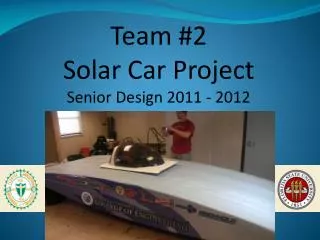
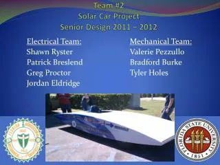
Senior Design Team 20Solar Powered Phase-Change Compressor Final Design Presentation April 18, 2013 Addison Bender Jesse Diaz Emmanuel Ferdinand Sponsor: Grant Peacock Faculty Advisor: Dr. Juan Ordonez and John Dascomb
Project Definition • Need Statement: • Design a compressor for a refrigeration system that can be powered by solar energy. • Objective: 5,000 BTU/hr (1465 W) • Solar-Thermal Driven • Budget: $2000 Final Design Presentation
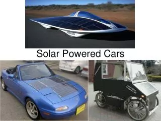
Concept Development • Solar energy → electricity → mechanical power • Solar energy → mechanical power Final Design Presentation
Concept Development • Piston • Pros: • High stress & high cycling • High temperature • Large displacement • Cons: • Precision machining • Possibility of refrigerant escaping Final Design Presentation
Concept Development • Elastic Membrane • Pros: • Larger tolerances • Sealed by non-permeable material • Cons: • High temperature • Fatigue effects • Smaller displacement Final Design Presentation
System Diagram Condenser Compressor Air Conditioner Capillary Refrigerant Loop / Steam Source Evaporator Steam Flow Fan Fan Control Control Circuit Microcontroller Power Supply (120V AC) Solenoid Valve Relay Steam vent Final Design Presentation
Design Concept • Vent is closed • Steam pressure compresses refrigerant • Vent is opened • Steam chamber pressure drops below refrigerant chamber pressure. • Vent is closed, cycle repeats. R134a From evaporator R134a to condenser High Pressure Steam from solar boiler Vented steam Final Design Presentation
Control Circuit for Solenoid Final Design Presentation • Arduino R3 Uno Microcontroller • Open and closed valve at 1 Hz • 2N222 Transistor and 5.6 kΩ Resistor • Solid State Relay • Control voltage (5 – 24 VDC) • Load Voltage (19-264 VAC) • Load Current (10 A)
Thermodynamic Model: Refrigeration Cycle T • Isentropic compression • Isobaric heat rejection • Adiabatic expansion • Isobaric heat absorption • ∆P = 433 kPa • m = 0.009 kg/s 1 3 4 2 T2 = 32.9°C P2 = 771 kPa T3 = 30°C P3 = 771 kPa T1 = 4°C P1 = 338 kPa T4 = 4°C P4 = 338 kPa s R134a Ideal Vapor-Compression Refrigeration Cycle Final Design Presentation
Modeling Diaphragm Deflection • Elasticity of material is used to predict deflection • V = 1.67 x 10⁻⁴ m3 • f = 2Hz • D = 12cm, δ = 2.7 cm, t = 1.3 cm D t δ Final Design Presentation
Sealing • Bolt material: steel • Yield strength = 45,000 psi • Tensile stress area = 0.025 in2 • Max chamber pressure = 150 psi • Load on bolts = P*A = 707 lb. • Load on 1 bolt =707N/6 = 117.8 lb. • Stress on 1 bolt = F/A = 4,713 psi Final Design Presentation
Testing Procedure • Static pressure test: 800kPa • Steam Test: membrane rupture • Connect to compressed air supply • Add refrigerant to selected pressure • Run solenoid at preset duty cycle • Increment air flow and monitor refrigerant pressure • Increase refrigerant pressure and repeat Final Design Presentation
Results Final Design Presentation
Results Final Design Presentation
Desired Solar Power • Thermal efficiency based on a dish size of 6.47 m2 • Theoretical solar concentrator would generate ~6,900 W Final Design Presentation
Failure Modes of Diaphragm Compressor Final Design Presentation
Feasibility of PCC • Duty cycle too high • 5 cycles/hour is considered HIGH for membrane • Design requires 3600 cycles/hour • Too much steam needed to generate 145 Watts • ($1-$3)/Watt for PV • $19.93/Watt for Actual Final Design Presentation
Summary • Compression was achieved, though less than target. • Membrane concept is much less stable than piston. • System is more prone to failure than solar-electric generation due to high use components. Final Design Presentation
Recommendations • Include a control valve to control steam in • Implement feedback control based on low and high pressure sensors • Test membrane component • Property degradation with high cycle loading • Performance at high temperature • Incorporate solar generated steam source Final Design Presentation