Download
1 / 6

E N D
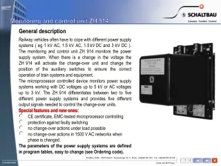
General description Railway vehicles often have to cope with different power supply systems ( eg 1 kV AC, 1.5 kV AC, 1.5kVDC and 3 kV DC ). The monitoring and control unit ZH 914 monitors the power supply system. When there is a change in the voltage the ZH914 will activate the change-over unit and change the position of the auxiliary switches to ensure the correct operation of train systems and equipment. The microprocessor controlled device monitors power supply systems working with DC voltages up to 5 kV or AC voltages up to 3kV. The ZH914 differentiates between two to five different power supply systems and provides five different output signals needed to control the change-over units. Special features and new ones: CE certificate, EMC-tested microprocessor controlling protection against faulty switching no change-over actions under load possible no change-over actions in 1500 V AC networks when phase is changed. The parameters of the power supply systems are defined in program tables, easy to change (see Ordering code).
Selection of voltage range: Ordering code 5 3 2 6 1 Table 2, safety check at the main heater with 500…1440 V, new features Table 1, safety check at the main heater with 500…1440 V, new features Table 2, safety check at the main heater with 500…1440 V Table 1, safety check at the main heater with 500…1440 V Table 1, safety check at the main heater with 0…1440 V Number of control-outputs for voltage ranges: 1 4: [1 kV AC], [1.5 kV AC], [1.5 kV DC], [3 kV DC] 2 5: [1 kV AC], [1.5 kV AC], [1.5 kV DC], [3 kV DC], [3 kV AC] 3 3: [1 kV AC], [1.5 kV AC & 1.5 kV DC], [3 kV DC] 4 3: [1 kV AC], [1.5 kV AC & 1.5 kV DC], [3 kV DC & 3 kV AC] Switch-off characteristics: N Normal switch-off characteristics Maximum switch-off voltage U max-off, according to table 1 or table 2, see selection voltage range E Extra switch-off characteristics Extra maximum switch-off point for 3 kV DC range, all other voltage ranges according to table 1 or table 2, see “Selection of voltage range” ZH 914 Control voltage of the device: 24 V DC according to UIC 120 16.8V … 158V Special features for 1 kV AC range: N 16 2/3 Hz and 50 Hz allowed I 16 2/3 Hz only Number of selected voltage ranges: 4 4: 1 kV AC, 1.5 kV AC, 1.5 kV DC, 3 kV DC 5 5: 1 kV AC, 1.5 kV AC, 1.5 kV DC, 3 kV DC, 3 kV AC
Name of Switch-on voltage Minimum voltage Maximum voltage Re-entry voltage Extra maximum power U switch-off point switch-off point ( switch-on point ) switch-off point min-on supply U = U U = min-off max-off max-on system U -X U + Y min-on max-off 1 kV AC 750V +/- 50V 50 - 80 V 1250 +/- 50V 50 - 80 V --- 1.5 kV DC 950V +/- 50V 50 - 80 V 1975 +/-75V 80 - 125 V --- Available program tables defining power supply systems Table 1: Definition of power supply systems of European coaches according to UIC550 1.5 kV AC 1100V +/- 50V 50 - 80 V 1860 +/- 75V 80 - 125 V --- 3 kV DC 1900V +/- 75V 50 - 125 V 4050 +/- 100V 150 - 250 V 4150V 3 kV AC 1900V +/- 75V 50 - 125 V 4050 +/- 100V 150 - 250 V --- Table 2: Definition of very special power supply systems of European coaches
244 250 230 208 8 23 6 160 180 Monitoring and control unit ZH 914 Dimension Diagram
Replacing ZH 714 types Note for replacing a ZH 714 type by a ZH 914 type: After each operation of the change-over unit all control units will test the correct position of the switches by switching on one part of the electrical heater. If there are 0V ... 1440 V the old ZH 814 type detects correct operation. The new ZH 914.1xx and ZH 914.2xx types, however, detect correct operation only if there are 500V...1440 V. This means that whenever the ZH 914 will be tested there has to be at least a minimum of 500 V at the test point.
Replacing ZH 814 types Note for replacing a ZH 814 type by a ZH 914 type: 1. After each operation of the change-over unit all control units will test the correct position of the switches by switching on one part of the electrical heater. If there are 0V ... 1440 V the old ZH 814 type detects correct operation. The new ZH 914.1xx and ZH 914.2xx types, however, detect correct operation only if there 500V...1440 V. This means that whenever the ZH 914 will be tested there has to be at least a minimum of 500 V at the test point. 2. The ZH 814 has a 8-pin connector, the ZH 914 has a 10-pin connector. So replacing a ZH 814 by a ZH 914 you always have to change the cable, too ( see table )!