Transport Layer Services and Protocols Overview
520 likes | 557 Views
Understand the principles of transport layer services including multiplexing, reliable data transfer, flow and congestion control in the internet. Learn about UDP and TCP connection-oriented and connectionless transport, efficient transfer, and congestion control mechanisms. Explore how transport layer protocols provide logical communication between application processes on different hosts enhancing network data transfer services. Discover the importance of multiplexing and demultiplexing in delivering segments to correct processes. Gain insights into UDP as a connectionless transport, its benefits, and the UDP checksum for error detection. Discussion on UDP servers and their iterative handling of client requests.

Transport Layer Services and Protocols Overview
E N D
Presentation Transcript
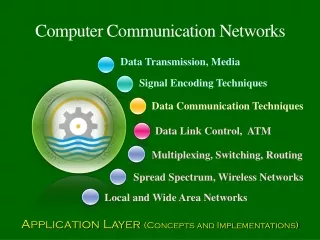
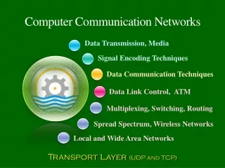
Computer Communication Networks Data Transmission, Media Signal Encoding Techniques Data Communication Techniques Data Link Control, ATM Multiplexing, Switching, Routing Spread Spectrum, Wireless Networks Local and Wide Area Networks Transport Layer (UDP and TCP)
Lecture Goals • Understand principles behind transport layer services: • multiplexing/demultiplexing • reliable data transfer • flow control • congestion control • Implementation in the Internet
Lecture Overview • Transport layer services • Multiplexing/demultiplexing • Connectionless transport: UDP • Connection-oriented transport: TCP • reliable transfer • flow control • connection management • TCP congestion control
Transport services and protocols • Providelogical communication between app’ processes running on different hosts • Transport protocols run in end systems • Transport vs. network layer services: • network layer: data transfer between end systems • transport layer: data transfer between processes • Relies on, enhances, network layer services
application transport network data link physical application transport network data link physical network data link physical network data link physical network data link physical network data link physical network data link physical logical end-end transport Transport Services and Protocols
Transport-layer protocols Internet transport services: • Reliable, in-order unicast delivery (TCP) • congestion • flow control • connection setup • Unreliable (“best-effort”), unordered unicast or multicast delivery: UDP • Services not available: • real-time • bandwidth guarantees • reliable multicast
Recall: segment- unit of data exchanged between transport layer entities aka TPDU: transport protocol data unit M M M M application transport network application transport network application transport network H n Multiplexing / demultiplexing Demultiplexing: delivering received segments to correct app layer processes receiver P3 P4 application-layer data segment header P1 P2 segment H t M segment
multiplexing/demultiplexing: based on sender, receiver port numbers, IP addresses source, dest port #s in each segment recall: well-known port numbers for specific applications Multiplexing: Multiplexing / demultiplexing gathering data from multiple app processes, enveloping data with header (later used for demultiplexing) 32 bits source port # dest port # other header fields application data (message) TCP/UDP segment format
Source IP: C Dest IP: B source port: x dest. port: 80 Source IP: C Dest IP: B source port: y dest. port: 80 Source IP: A Dest IP: B source port: x dest. port: 80 source port:23 dest. port: x source port: x dest. port: 23 Multiplexing/demultiplexing: examples Web client host C server B host A port use: simple telnet app Web server B Web client host A port use: Web server
UDP: User Datagram Protocol [RFC 768] • “no frills,” “bare bones” Internet transport protocol • “best effort” service, UDP segments may be: • lost • delivered out of order to app • connectionless: • no handshaking between UDP sender, receiver • each UDP segment handled independently of others
UDP: User Datagram Protocol [RFC 768] Why is there a UDP? • no connection establishment (which can add delay) • simple: no connection state at sender, receiver • small segment header • no congestion control: UDP can blast away as fast as desired. • May not be a good idea, though!
UDP: more • Often used for streaming multimedia apps • loss tolerant • rate sensitive • Other UDP uses (why?): • DNS • SNMP • Reliable transfer over UDP: add reliability at application layer • application-specific error recovery!
UDP: more 32 bits source port # dest port # Length, in bytes of UDP segment, including header checksum length Application data (message) UDP segment format
Parity Checks 1 0 1 1 1 0 1 0 1 2 3 4 5 6 7 8 9 Odd Parity 1 0 1 1 1 0 1 0 0 0 0 1 1 1 0 1 0 0 1 2 3 4 5 6 7 8 9 1 2 3 4 5 6 7 8 9 1-bit error 0 0 0 1 0 0 1 0 0 0 0 0 1 1 0 1 0 0 1 2 3 4 5 6 7 8 9 1 2 3 4 5 6 7 8 9 3-bit error 2-bit error Even Parity 1 0 1 1 1 0 1 1 0 1 2 3 4 5 6 7 8 9 Parity can detect 1-bit errors
UDP checksum Goal: detect “errors” (e.g., flipped bits) in transmitted segment Sender: • treat segment contents as sequence of 16-bit integers • checksum: addition (1’s complement sum) of segment contents • sender puts checksum value into UDP checksum field
UDP checksum Receiver: • compute checksum of received segment • check if computed checksum equals checksum field value: • NO - error detected • YES - no error detected. • But maybe errors nonetheless?
UDP Servers • Most UDP servers are “iterative” => a single server process receives and handles incoming requests on a “well-known” port. • Can filter client requests based on incoming IP/port addresses or wild card filters • Port numbers may be reused, but packet is delivered to at most one end-point. • Queues to hold requests if server busy
Important in app., transport, link layers top-10 list of important networking topics! Principles of Reliable Data Transfer • Characteristics of unreliable channel will determine complexity of reliable data transfer protocol (rdt)
Reliability mechanisms… • Mechanisms: • Checksum in pkts: detects pkt corruption • ACK: “packet correctly received” • NAK: “packet incorrectly received” • [aka: stop-and-waitAutomatic Repeat reQuest (ARQ) protocols] • Reliability capabilities achieved: • An error-free channel • A forward channel which has bit-errors
TCP: Overview • Point-to-point: • one sender, one receiver • Reliable, in-order byte steam: • no “message boundaries” • But TCP chops it up into segments for transmission internally • Pipelined (window) flow control: • Window size decided by receiver and network • Send & receive buffers
TCP: Overview • Full duplex data: • bi-directional data flow in same connection • MSS: maximum segment size • Connection-oriented: • handshaking (exchange of control msgs) init’s sender, receiver state before data exchange • Flow & Congestion Control: • sender will not overwhelm receiver or the network
32 bits source port # dest port # sequence number acknowledgement number head len not used rcvr window size U A P R S F checksum ptr urgent data Options (variable length) application data (variable length) TCP segment structure URG: urgent data (generally not used) counting by bytes of data (not segments!) ACK: ACK # valid PSH: push data now (generally not used) # bytes rcvr willing to accept RST, SYN, FIN: connection estab (setup, teardown commands) Internet checksum (as in UDP)
TCP seq. #’s and ACKs (I) Sequence Numbers: • byte stream “number” of first bytein segment’s data ACKs: • seq # of next byte expected from other side • cumulative ACK Q: how receiver handles out-of-order segments • A: TCP spec doesn’t say, - up to implementor
TCP Seq. #’s and ACKs (II) Host B Host A User types ‘C’ Seq=42, ACK=79, data = ‘C’ host ACKs receipt of ‘C’, echoes back ‘C’ Seq=79, ACK=43, data = ‘C’ host ACKs receipt of echoed ‘C’ Seq=43, ACK=80 simple telnet scenario
Temporal Redundancy Model Packets • Sequence Numbers • CRC or Checksum Timeout • ACKs • NAKs, Status Reports Retransmissions • Packets • FEC information
Status Report Design • Cumulative acks: • Robust to losses on the reverse channel • Cannot pinpoint blocks of data which are lost • The first lost packet can be pinpointed because the receiver would generate duplicate acks
TCP ACK generation TCP Receiver action delayed ACK. Wait up to 500ms for next segment. If no next segment, send ACK immediately send single cumulative ACK send duplicate ACK, indicating seq. # of next expected byte Event in-order segment arrival, no gaps, everything else already ACKed in-order segment arrival, no gaps, one delayed ACK pending out-of-order segment arrival higher-than-expect seq. # gap detected!
Host A Host B Host A Host B Seq=92, 8 bytes data Seq=92, 8 bytes data Seq=100, 20 bytes data ACK=100 Seq=92 timeout timeout X ACK=100 Seq=100 timeout ACK=120 loss Seq=92, 8 bytes data Seq=92, 8 bytes data ACK=120 ACK=100 premature timeout, cumulative ACKs time time lost ACK scenario TCP: retransmission scenarios
receiver:explicitly informs sender of free buffer space RcvWindow field in TCP segment sender:keeps the amount of transmitted, unACKed data less than most recently received RcvWindow flow control TCP Flow Control sender won’t overrun receiver’s buffers by transmitting too much, too fast RcvBuffer = size or TCP Receive Buffer RcvWindow = amount of spare room in Buffer receiver buffering
TCP Connection Management - 1 Recall: TCP sender, receiver establish connection before exchanging data segments • initialize TCP variables: • seq. #s • buffers, flow control info (e.g. RcvWindow) • client: connection initiator Socket clientSocket = new Socket("hostname","port number"); • server: contacted by client Socket connectionSocket = serverSocket.accept();
TCP Connection Management - 2 Three way handshake: Step 1: client end system sends TCP SYN control segment to server • specifies initial seq # Step 2: server end system receives SYN, replies with SYNACK control segment • ACKs received SYN • allocates buffers • specifies server-> receiver initial seq. #
TCP Connection Management - 3 Closing a connection: client closes socket:clientSocket.close(); Step 1:client end system sends TCP FIN control segment to server Step 2:server receives FIN, replies with ACK. Closes connection, sends FIN.
client server close FIN ACK close FIN ACK timed wait closed TCP Connection Management - 4 Fddfdf d
TCP Connection Management - 5 Step 3:client receives FIN, replies with ACK. • Enters “timed wait” - will respond with ACK to received FINs Step 4:server, receives ACK. Connection closed. Note: with small modification, can handle simultaneous FINs.
The Congestion Problem • Problems: • Incomplete information (eg: loss indications) • Distributed solution required • Congestion and control/measurement locations different • Time-varying delays
S S S S The Congestion Problem • Static fixes may not solve congestion • a) Memory becomes cheap (infinite memory) No buffer Too late • b) Linksbecome cheap (high speed links)? Replace with 1 Mb/s All links 19.2 kb/s S S S S File Transfer time =5 mins File Transfer Time =7 hours
The Congestion Problem (Continued) • c) Processors become cheap (resulting in faster routers & switches) A C S B D Scenario: All links 1 Gb/s. A & B send to C => “high-speed” congestion!! (lose more packets faster!)
Principles of Congestion Control Congestion: • informally: “too many sources sending too much data too fast for network to handle” • different from flow control (receiver overload)! • symptoms: • lost packets (buffer overflow at routers) • long delays (queuing in router buffers) • a top-10 problem!
two senders, two receivers one router, infinite buffers no retransmission Causes/costs of congestion: scenario 1 • large delays when congested • maximum achievable throughput
one router, finite buffers sender retransmission of lost packet Causes/costs of congestion: scenario 2
Causes/costs of congestion: scenario 2 (continued) “Costs” of congestion: • More work (retrans) for given “goodput” • Unneeded retransmissions: link carries multiple copies of pkt due to spurious timeouts
Causes/costs of congestion: scenario 3 Another “cost” of congestion: • when packet dropped, any “upstream transmission capacity used for that packet was wasted!
Approaches towards congestion control - 1 • Two broad approaches towards congestion control: End-end congestion control: • no explicit feedback from network • congestion inferred from end-system observed loss, delay • approach taken by TCP
Approaches towards congestion control - 2 Network-assisted congestion control: • routers provide feedback to end systems • single bit indicating congestion (SNA, DECbit, TCP/IP ECN, ATM) • explicit rate sender should send at
TCP congestion control - 1 • end-end control (no network assistance) • transmission rate limited by congestion window size, Congwin, over segments:
TCP congestion control - 2 • “Probing” for usable bandwidth: • Windowflow control: avoid receiver overrun • Dynamic window congestion control: avoid/control network overrun • Policy: • Increase Congwin until loss (congestion) • Loss => decrease Congwin, then begin probing (increasing) again
Additive Increase/Multiplicative Decrease (AIMD) Policy • For stability: • rate-of-decrease > rate-of-increase • Decrease performed “enough” times as long as congestion exists • AIMD policy satisfies this condition, provided packet loss is congestion indicator window time
Fairness Fairness goal: if N TCP sessions share same bottleneck link, each should get 1/N of link capacity TCP connection 1 bottleneck router capacity R TCP connection 2
TCP latency Q:How long does it take to receive an object from a Web server after sending a request? • TCP connection establishment • data transfer delay