Download
1 / 21
290 likes | 747 Views
Digital Energy Multilin. Problems and Solutions of Line Differential Application in Cable Transformer Protection. Jorge Cardenas. GE Digital Energy Mahesh Kumar. GE Digital Energy Jesus Romero. RasGas. CIGRE 7-10 September 2009, Moscow. Application problem in differential Cable+Transformer.

E N D
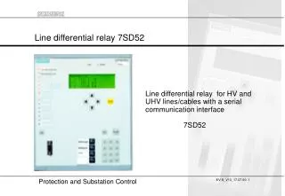
Digital EnergyMultilin Problems and Solutions of Line Differential Application in Cable Transformer Protection Jorge Cardenas. GE Digital EnergyMahesh Kumar. GE Digital EnergyJesus Romero. RasGas CIGRE 7-10 September 2009, Moscow
Application problem in differential Cable+Transformer Transformer Inrush phenomena affects the operation of the differential protection in the same way as in case of a Power Transformer. In the classical approach, an inhibition or blocking action based on the harmonic (usually 2nd harmonic) content on the differential algorithm, is normally used. Because differential protection is practically disabled during some time after the energization, a complementary protection is needed to disconnect the circuit if a fault is produced during that time Another problem is the Inrush phenomena after the voltage recovery during external three-phase or phase-to-phase faults..
Initial Protection Scheme As Current Differential Relays installed in the plant have not specific functions to prevent Transformer Inrush phenomena, initially a logic based on setting group change was implemented to avoid a non-desirable trip when the Line is energized (there are no CB´s on the 33 kV receiving end of the individual Power Transformers) and interposing CT’s are used at LV side to correct the vectors similar to conventional transformer differential protection. At time zero, the relays work with a high pickup differential settings (typically 2.0 p.u.) and with a time delay (800 ms) after the CB close, the pickup is changed to a lower value (typically 0.3 p.u.).
Initial Logic to prevent false trip during energization Relays (UR from GE) installed allows on-line logic change of the differential pickup level. Setting Group is changed in less than 2.5 ms. This is the maximum additional delay expected to trip on internal faults.
Problems with the Initial Protection Scheme • Definition was correct, but incomplete. Logic only contemplates Energization, but no Inrush after voltage recovery. • Pickup setting were too low for Energization, particularly on 6.6 kV. Side • No complementary protection was active to prevent faults during the energization, only TOC as backup.
Changes Recommended 1. Switch on to fault and distance protections implemented in Setting Group 2 to provide backup to current differential protection during transformer energizing or when operation is blocked due to loss in communications. This new setting effectively covered all 3 phase and phase to phase faults up to 120% of the line. Ground TOCs in 33KV and 6.6KV provide the protection for phase to ground fault as per existing settings. The current differential pickup is adjusted to avoid unwanted trip due to inrush currents. 2. Setting Group 3 is introduced in the scheme to provide the correct setting for inrush current produce during voltage recovery after the isolation of an external fault. The new setting used distance protection to cover 3 phase and phase to phase internal faults. Ground TOCs in 33KV and 6.6KV cover phase to ground faults as the actual coverage is done with Setting Group 1. 3. Distance protection is implemented in Setting Group 1 to cover all faults up to transformer HV windings, this also provided backup to current differential protection when the operation is blocked due to loss of communications.
4. With the existing or proposed current differential settings in Group 1, it was found out that for loads in 33KV of more than 200A approximately, differential protection does not operate on phase to ground faults. This is due to the increased in the restraint current magnitudes with increased load currents. Enabling of distance Gnd Z2 proved to address this problem plus the existing 33KV directional Ground TOC. It has also been noted that only trip on current differential is programmed for circuit breaker inter trip. A new inter trip logic based also in the other protection functions (Distance, SOFT and Ground TOC) has been tested and it is recommended for implementation. The Solutions Proposed were validated initially with test on RTDS ans later with tests in Field. Changes Recommended (cont.)
Validation of the model for Inrush tests a) Phase A b) Phase B c) Phase C
New Setting Group Proposed for Inrush recovery after external faults Modifications in Group 2 were as follows: Relay at 33 kV: Change the slope 2 to 70% and the Breakpoint to 2 Relays at 6.6 kV: Raise the pickup to 4.0, slope 2 to 70% and Breakpoint to 2 Critical Irest vs Idiff in 6.6 kV modified Setting of Group 2
New Setting Group Proposed for Inrush recovery after external faults It was decided an intermediate setting, higher than the maximum peak estimated according to table 1 (3,2 p.u.). Settings on relays at 33 kV and 6.6 kV were as follows:
Logic Implemented to complement the Line Differential Algorithm
Energization tests in the worst close angle condition after the new logic implementation
Inrush voltage recovery tests after the new logic implementation Inrush after voltage recovery. Operation considering load condition, that is trip on external fault caused by an instantaneous protective relay. 3PH fault on 1
Cable and Transformers Fault tests PH_PH fault on pos 5. PH-PH in Pos 7. 3PH in pos 7. External 3PH fault on 6.
Cable and Transformers Fault tests Direct trip by Ground TOC and Distance during internal PH_G fault on 4.
Conclusions • Proposed solution makes the energization of transformers without any nuisance trips and proved several time for last 2 years. As these feeders were crucial in LNG production of Rasgas, this solution helped them to save time and money with an improved reliability. • The solution implemented has been be extended to any other similar substations w/o additional hardware, nor modifications on it. • The numeric technology in the multifunction relays give us many tools to implement new solutions to problems that in the past were only possible to solve using another techniques as the second harmonic restrain to prevent a false trip during transformer energization. We have demonstrated that other possible schemes are also possible maintaining a similar level of reliability and security as the traditional ones. • The use of the RTDS has allowed as a very good approach with the problems encountered in field, helping in test new solution for Differential Application on schemes composed by cables + transformers.