Download
1 / 30
320 likes | 625 Views
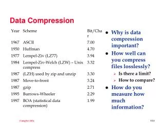
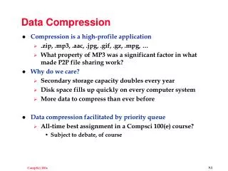
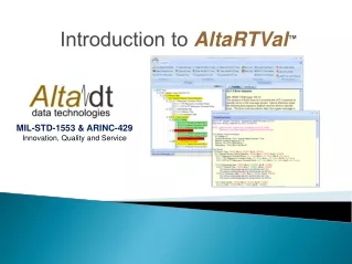
Application of Data Compression to the MIL-STD-1553 Data Bus. Scholar’s Day Feb. 1, 2008 By Bernard Lam. Overview. Background MIL-STD-1553 Bus Trace Analysis Solutions – Compression Algorithms Zero-Tracking, Modified Run-Length, and Differential Error Analysis

E N D
Application of Data Compression to theMIL-STD-1553 Data Bus Scholar’s Day Feb. 1, 2008 By Bernard Lam
Overview • Background • MIL-STD-1553 • Bus Trace Analysis • Solutions – Compression Algorithms • Zero-Tracking, Modified Run-Length, and Differential • Error Analysis • Conclusions & Future Research
Goal Of Research • To extend the bandwidth capabilities of MIL-STD-1553 Bus, using compression techniques. • Develop algorithms suitable for legacy systems • Demonstrate that the time to compress and decompress data is offset by the overall savings in data transmission time.
Timing Analysis Timing Diagram
Background ~ MIL-STD-1553 • MIL-STD-1553 serial data bus • Developed in the late 1960’s and early 1970’s • Limited/Low Bandwidth • 1 Mb/s • Has lead to development of multiple independent busses • Time division multiple (TDM) access System Model
Background ~ MIL-STD-1553 • MIL-STD-1553 (cont’d) • Manchester Bi-phase encoding • Data word size: 16 bit • Sync Waveform • Parity Bit Message Format
Background ~ MIL-STD-1553 • MIL-STD-1553 (cont’d) • Max. single-command transmission size of 32 words • Safety and Mission Critical System • Real-Time System • Replacement of MIL-STD-1553 with updated bus protocol, such as Fibre Channel, not a viable solution because of extensive costs.
Bus Trace Analysis • Analysis was conducted using data from multiple bus traces of data captured at the F/A – 18 Advanced Weapons Laboratory. • Each trace represented roughly 30 seconds of flight data and included examples of mode changes and start-up conditions.
Bus Trace Analysis • Significant amount of zeros Percent of Zeros 20 Hz 10 Hz 5 Hz Max % Zeros 96.3% 90.1% 78.6% Min % Zeros 53.5% 88.5% 72.0% Avg. % Zeros 68% 88.8% 73.5%
Bus Trace Analysis • Limited number of changes between consecutive message transmissions Percent of Changes 20 Hz 10 Hz 5 Hz Max % Changes 21.7% 27.5% 78.6% Min % Changes 2.0% 0% 2% Avg. % Changes 3.9% 3.3% 3.3%
Data Compression • Lossless vs. Lossy Compression • Lossless • Original data is completely retrievable by means of decompression • Ex. Winzip, GIF • Lossy • Lose information; original data not retrievable when decompressed • Higher Compression Ratios • E.g., jpeg, mpeg, mp3
FFFF FFFF FFFF xxxx FFFF AFC1 yyyy AFC1 compress decompress AFC1 AFC1 Data Compression • Coding Performance and Efficiency • Measured by compression ratio
Data Compression • Criteria • Lossless Compression • Take advantage of message format of MIL-STD-1553 • Limit worst case expansion • Limit computational and memory requirements
Compression Algorithms • Common Value Tracking • Zero-Tracking • Modified Run-Length Encoding • Differential Encoding
Zero Tracking • Encodes long sequences containing mostly zeros • Uses marker sequence to indicate the position of zeros • Transmits • Position Address (marker sequence) • Non-Zero Data Words
Bit Position Word 1 0 1 1 Zero-Tracking Encoding (Example) Word Count (Hex) Input Data (Hex) ZT Encoded Data (Hex) 0 0 1 CBD0 1 0 1 FFFF 2 FFFF 0 59 3 59 0 AC9F 4 0 486 5 AC9F 6 0 7 0 1 8 0 1 9 0 A 486 0 B 0 1
Zero Tracking • If a 32-word block is compressed • 2 data words are required to indicate positions • Can transmit maximum of 31 uncompressed data words • Most significant bit in 1st address word is used to indicate if uncompress/compressed • Worst Case Compression Ratio • comp. ratio = 31/32
Modified Run-Length Encoding • Encodes consecutive sequences of identical words • Uses marker sequence to indicate the presence of repeated sequences within block set • For block of 32 words • Worst Case Expansion – 31/32
Bit Position Word Modified Run-Length (Example) Word Count (Hex) Input Data (Hex) RT Encoded Data (Hex) 0 0 0 67A0 1 0 1 0 2 0 1 FFFF 3 FFFF 0 5604 0 4 5604 9840 1 5 5604 B1F4 1 6 5604 1 7 5604 1 8 5604 0 9 9840 A 9840 1 B B1F4 0
Differential Encoding • Encodes only changes of previous vs. current word locations • A differential scheme takes advantage of the fact that for a given rate group one transmission to the next does not change • Two buffers are required for comparison of previous and current transmissions
Bit Position Word Differential Encoding Word Count (Hex) Previous Data (Hex) Current Data (Hex) DT Encoded Data (Hex) 0 0054 0054 0 20D0 1 0815 0815 0 12F8 2 AF58 12F8 1 9FB2 3 0000 0000 0 FDA9 4 0000 0000 0 A14F 5 6542 6542 0 6 FFFF FFFF 0 7 FFFF FFFF 0 8 2222 9FB2 1 9 8966 FDA9 1 A 8966 8966 0 B 0052 A14F 1
Compression Ratios Average Compression Ratios For Algorithms 20 Hz 10 Hz 5 Hz MC1 MC2 MC1 MC2 MC1 MC2 Zero-Tracking 2.63 1.66 4.65 3.39 2.44 2.60 Mod. Run-Length 1.34 1.97 2.44 2.80 2.13 1.17 Differential 12.47 5.74 14.47 7.22 8.37 1.31
Compression Bit Status • 1st Bit of 1st 16-bit word indicates the compression status • ‘1’ - equals uncompressed • ‘0’ – equals compressed Block Set Format Compression Status Bit Position Word Bit Position Word 31 – 16 bit Data Words 30 – 16 bit Data Words
Transmission Error Effects • Effects of data errors can be amplified when using data compression • If higher levels of error detection and correction (EDAC) are needed, one or more data words can be dedicated to EDAC
Transmission Error Effects • Standard 1553 Error Checking • Bit Errors can be detected • Exception – multiple-bit errors without parity change cannot be detected • Common Value Tracking • If an undetected error is in the bit position word, multiple words can be corrupted. • If an undetected error is in the data word, only that word location is impacted
Transmission Error Effects • Modified Run-Length Compression • Like zero tracking a error in the bit position word can invalidate a run • Error dramatically worse result than that of zero-tracking • Differential Encoding • Error in address word can result incorrect updating • Worst Case – All data words are updated • Further Research Required
Future Research • Error Handling Routines • Effects of mode-changing and start-up • Timing analysis for Run-Length and Differential Encoding
Conclusions • Reviewed Statistical Analysis of Trace Data • Able to achieve compression ratios greater than one for all algorithms • Discussed Error Analysis • Preliminary timing simulations of timing look promising
Acknowledgements • Dr. Russell Duren • Dr. Michael Thompson