Download
1 / 63
630 likes | 889 Views
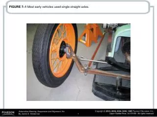
FIGURE 7–1 Most early vehicles used single straight axles. FIGURE 7–2 Typical kingpin used with a solid axle. FIGURE 7–3 Twin I-beam front suspension. Rubber bushings are used to support the I-beams to the frame and help isolate road noise.

E N D
FIGURE 7–3 Twin I-beam front suspension. Rubber bushings are used to support the I-beams to the frame and help isolate road noise.
FIGURE 7–4 The rubber radius rod bushing absorbs road shocks and helps isolate road noise.
FIGURE 7–5 The upper control arm is shorter than the lower control arm on a short/long-arm (SLA) suspension.
FIGURE 7–6 A typical SLA front suspension using coil springs.
FIGURE 7–7 An SLA-type suspension with the coil spring placed on top of the upper control arm.
FIGURE 7–8 A torsion bar SLA suspension can use either the lower or the upper control arm.
FIGURE 7–9 A typical MacPherson strut showing all of the components of the assembly. A strut includes the shock and the spring in one structural assembly.
FIGURE 7–10 The modified strut front suspension is similar to a MacPherson strut suspension except that the coil spring is seated on the lower control arm and is not part of the strut assembly.
FIGURE 7–11 Multilink front suspension design varies depending on the vehicle manufacturer.
FIGURE 7–12 A leaking strut. Either a cartridge insert or the entire strut will require replacement. If a light film of oil is seen, this is to be considered normal. If oil is dripping, then this means that the rod seal has failed.
FIGURE 7–13 This front coil spring looks as if it has been heated with a torch in an attempt to lower the ride height of the vehicle. Both front springs will require replacement.
FIGURE 7–14 It is easy to see that this worn control arm bushing needed to be replaced. The new bushing is shown next to the original.
FIGURE 7–15 Grease fitting projecting down from the surrounding area of a ball joint. The ball joint should be replaced when the area around the grease fitting is flush or recessed.
FIGURE 7–16 Indicator ball joints should be checked with the weight of the vehicle on the ground.
FIGURE 7–17 Typical dial indicator used to measure the suspension component movement. The locking pliers attach the gauge to a stationary part of the vehicle and the flexible coupling allows the dial indicator to be positioned at any angle.
FIGURE 7–18 If the spring is attached to the lower control arm as in this SLA suspension, the jack should be placed under the lower control arm as shown. A dial indicator should be used to measure the amount of freeplay in the ball joints. Be sure that the looseness being measured is not due to normal wheel bearing endplay.
FIGURE 7–19 The jack should be placed under the lower control arm of this modified MacPherson-type suspension.
FIGURE 7–20 If the spring is attached to the upper control arm, the jack should be placed under the frame to check for ball joint wear.
FIGURE 7–21 A special tool or a block of wood should be inserted between the frame and the upper control arm before lifting the vehicle off the ground. This tool stops the force of the spring against the upper ball joint so that a true test can be performed on the condition of the ball joint.
FIGURE 7–22 The jacking point is under the frame for checking the play of a lower ball joint used with a MacPherson strut.
FIGURE 7–23 This worn and rusty ball joint was found by moving the wheel and looking for movement in the joint.
FIGURE 7–24 Taper breaker tool being used to separate the upper ball joint from the steering knuckle. This is especially important for vehicles equipped with aluminum alloy control arms.
FIGURE 7–25 A pinch bolt attaches the steering knuckle to the ball joint. Remove the pinch bolt by turning the nut, not the bolt.
FIGURE 7–26 If the pinch bolt is overtightened, the steering knuckle can be deformed. A deformed knuckle can cause the pinch bolt to break and the ball joint could become separated from the steering knuckle.
FIGURE 7–27 By drilling into the rivet, the holding force is released.
FIGURE 7–28 The head of the rivet can be removed by using a larger-diameter drill bit as shown.
FIGURE 7–29 Using a punch and a hammer to remove the rivet after drilling down through the center and removing the head of the rivet.
FIGURE 7–30 Press-in ball joints are best removed using a large C-clamp press, as shown.
FIGURE 7–34 Most shock absorbers used on the front suspension can be removed from underneath the vehicle after removing the attaching bolts or nuts.
FIGURE 7–35 Removing the upper strut mounting bolts. Some experts recommend leaving one of the upper strut mount nuts loosely attached to prevent the strut from falling when the lower attaching bolts are removed.
FIGURE 7–36 A brake hydraulic hose is often attached to the strut housing. Sometimes all that is required to separate the line from the strut is to remove a spring clip.
FIGURE 7–37 Use a strut spring compressor fixture to compress the spring on a MacPherson strut before removing the strut retaining nut.
FIGURE 7–38 Removing the strut rod nut. The strut shaft is being helped with one wrench while the nut is being removed with the other wrench. Notice that the spring is compressed before the nut is removed.
FIGURE 7–39 Typical MacPherson strut showing the various components.
FIGURE 7–40 After installing the replacement strut cartridge, reinstall the spring and upper bearing assembly after compressing the spring. Notice that the strut is being held in a strut spring compressor fixture.
FIGURE 7–41 Before final assembly, make sure the marks you made are aligned. Some struts are manufactured with marks to ensure proper reassembly.
FIGURE 7–42 The strut on a modified MacPherson strut assembly can be replaced by removing the upper mounting nuts.
FIGURE 7–43 Stabilizer bar links should be replaced as a pair.
FIGURE 7–44 A strut rod as viewed from the front of the vehicle.
FIGURE 7–45 Typical strut rod bushing with rubber on both sides of the frame to help isolate noise, vibration, and harshness from being transferred to the passengers.
FIGURE 7–46 Notice that if the front coil springs are sagging, the resulting angle of the lower control arm causes the wheels to move from side to side as the suspension moves up and down. Note the difference between the distance at “A” with good springs and the distance at “B” with sagging springs.
FIGURE 7–47 Spring compressing tool in place to hold the spring as the ball joint is separated. Note that the stabilizer bar links have been removed to allow the lower control arm to move downward enough to remove the coil spring.
FIGURE 7–48 The steering knuckle has been disconnected from the lower ball joint. The lower control arm and coil spring are being held up by a floor jack.
FIGURE 7–49 A rubber mallet is being used to support the upper control arm as the lower control is being lowered using a floor jack. After all of the tension has been removed from the coil spring it can be removed and the replacement installed.
FIGURE 7–50 Spring insulators install between the spring seat and the coil spring to reduce noise.