Download
1 / 6
60 likes | 185 Views
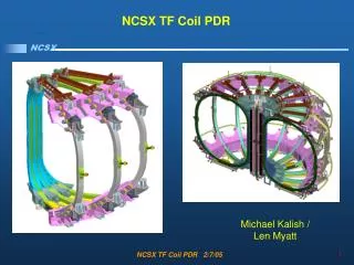
Analysis of Coil Structures Integrated Modular, TF and PF Modeling. Work by HM Fan. Status. Modeling of Integrated Structure Completed and debugged Mostly Linear except for Wing Interfaces Runs on existing 32 bit, 2GB computer platforms in ~ 14 hrs Four load cases run so far:

E N D
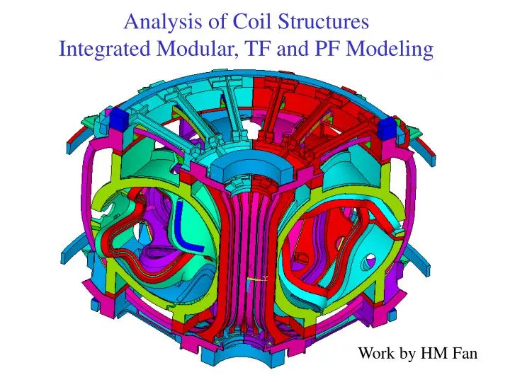
Analysis of Coil StructuresIntegrated Modular, TF and PF Modeling Work by HM Fan
Status • Modeling of Integrated Structure Completed and debugged • Mostly Linear except for Wing Interfaces • Runs on existing 32 bit, 2GB computer platforms in ~ 14 hrs • Four load cases run so far: • Gravity (Deadload) Only at RT • Gravity plus Cooldown to 80K • Gravity, Cooldown and EM (2T) • Gravity and EM (2T) • Thermal strain during pulse assumed to cancel cooldown strain • Interest is in understanding impact on MCWF Joints • Results post-processing still in progress
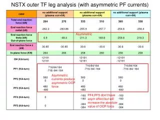
Results Comparison – Impact of Integrated Structure(for EM Only Load Case) Note: Not a true apples to apples comparison since effective conductor stiffness differs
Thermal Strain from Cooldown has only Small Impact on Loads at Flanges
Shear at Unbolted IL of MCWF Flanges Max Shear Top/Bot is 590 KN (133 Klbs)
Future Work • Addition runs to assess impact of modeling assumptions • Modular Coil and TF Coil Conductors assumed bonded • TF structure rigidly coupled to MCWF • Support Locations • Additional Load Cases to verify present case (2T) is worse case • Extract useful data for Support Design