eRHIC ZDR Design
200 likes | 218 Views
This report provides a detailed study on the design of the eRHIC collider, including the accelerator and interaction region. It covers goals, beam parameters, luminosities, and design options. Collaboration between BNL, MIT-Bates, BINP, and DESY. Link to report: www.agsrhichome.bnl.gov/eRHIC/eRHIC_ZDR.htm. Contact vadimp@bnl.gov to order copies.

eRHIC ZDR Design
E N D
Presentation Transcript
eRHIC ZDR Design V.Ptitsyn
Detailed document (265 pages) reporting studies on the accelerator and the interaction region of this future collider. • The work performed jointly by BNL and MIT-Bates, with close collaboration with scientists from BINP (Novosibirsk) and DESY (Hamburg). • Goals: • to develop an initial design for eRHIC • to investigate most important accelerator physics issues • to evaluate the luminosities that could be achieved in such a collider The report web links: • www.agsrhichome.bnl.gov/AP/ap_notes/ap_note_142.pdf • www.agsrhichome.bnl.gov/eRHIC/eRHIC_ZDR.htm To order copies: vadimp@bnl.gov
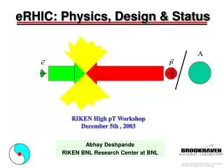
eRHIC scope • Experiments with electron-proton and electron-ion collisions. • Should be able to provide the beams in following energy ranges: • 5-10 GeV polarized electrons; 10 GeV polarized positrons • 50-250 GeV polarized protons; 100 GeV/u gold ions • Other ion species, especially polarized 3He ions are under consideration. • Luminosities: • in 1032 - 1033 cm-2s-1 region for e-p • in 1030 - 1031 cm-2s-1 region for e-Au collisions • 70% polarization degree for both lepton and proton beams • Longitudinal polarization in the collision point for both lepton and proton beams
e-cooling 5-10 GeV static electron ring recirculating linac injector RHIC EBIS BOOSTER AGS LINAC Main design option • The electron ring of 1/3 of the RHIC ion ring circumference • Full energy injection using polarized electron source and 10 GeV energy linac. • e-ion collisions in one interaction point. Ion-ion collisions in two other IPs at the same time. • Longitudinal polarization produced by local spin rotators in interaction regions.
Luminosity considerations • Luminosity limitation comes from beam-beam effects and from interaction region magnet aperture: • Beam-beam limits (from world experience, RHIC operation experience and initial beam-beam simulation results): xe < 0.08, xi < 0.02 (total from all collision points) • From interaction region design : mradand K=1/2 (sy/sx beam size ratio; elliptical beams) • Matched electron and ion beam sizes at the IP • fc =28.15 MHz : 360 bunches in the ion ring, 120 bunches in the electron ring
Collision parameters for e-p collisions No cooling 2 p-p IPs assumed Cooling needed No p-p IPs allowed
Basic beam parameters for e-Au collisions Electron cooling of Au beam is required to achieve and maintain Au emittance values
Electron Accelerator Design • The design development led by MIT-Bates. • The principal goal for ZDR was to create design using today’s established state-of-the-art reliable accelerator technology, without an extensive R&D program. • eRHIC electron ring is close in energy and beam parameters to e+e- B-factories. Accelerator physics experience and technological developments of B-factories have been used in the work on some critical design aspects of the eRHIC electron ring (RF system, synchrotron radiation load accommodation, evaluation of beam instabilities and remedies against them…)
Specific issues of eRHIC Electron Ring ZDR: F.Wang, D.Wang 1) Shape of electron beam in the interaction point should match the shape of ion beam for different collision energies used. Range of required rms emittance variation ~ 40-130 nm Flexible FODO arc structure for electron beam provides necessary emittance adjustment. Issues of optimal chromaticity corrections with acceptable dynamic aperture for different FODO cell phase advances used. 2) Also follows from 1) : High emittance ratio of the elliptical electron beam at the IP. For different collision energy scenariosk=ey/exvaries from 0.18 to 0.45. Not usual for electron rings. a) The control of global coupling by skew-quadrupoles OR b) Flat to elliptical beam transformation by “emittance” adaptor like scheme . More studies needed including experimental one. DA tracking from SAD code. (A.Otboev)
Red: normal FODO Cells Blue: chicane line Path length adjustment ZDR: C.Tschalaer Electron path length adjustment up to 0.2m. To adjust for proton revolution frequency variation in the proton energy range from 50 to 250 GeV Possible solution: magnetic chicanes path length in the arcs. Eight bend chicane produces 8.25cm difference. Issues: increased radiation power density
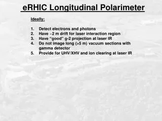
Electrons: depolarization in spin resonance zones (betatron and synchrotron resonances) Requirements for good vertical alignment and precise orbit control: yco rms < 50 mm ; Vertical dipole correctors and BPMs at each quadrupole magnet Positrons: self-polarized in the ring : tpol = 20min at 10 GeV; tpol ~ E-5 Spin rotator design uses high-field superconducting solenoids. Spin matched to avoid depolarization. Issues: Minimize depolarization of electron beam Build-up polarization for 10 GeV positron beam Accommodate spin rotators Electron polarization (ZDR: D.P. Barber, A.V. Otboev, Yu.M. Shatunov) 10 GeV SLICK code calculations (D.P. Barber)
Electron Injector (developed by MIT-Bates) • Full energy, polarized electron beam injector with flexible bunch to bunch filling capacity. Feasible for top-off and continuous injection. • Four possible designs considered: • Recirculating copper S-band linac • Recirculating superconducting linac • Figure-eight booster synchrotron • FFAG synchrotron (D.Trbojevic et al) Main injector parameters
Required ion ring upgrades Ion ring upgrades considered in the report: • Electron cooling, to provide and maintain the required beam emittances • Total ion current intensity increase, by increasing the number of bunches from 120 (present RHIC design) to (ultimately) 360. • Additional spin rotators in e-p interaction region. 360 bunches (35ns bunch spacing) issues: • Injection scheme upgrade (ZDR: W. Fischer, M. Blaskiewicz, J.M. Brennan, H. Hahn) Very fast injection kicker (~20 ns risetime) or Long flattop injection kicker or Barrier RF Stacking • Abort system upgrade(ZDR: L.Ahrens) • Cryogenic power load (due to beam pipe heating)(ZDR: V.Ptitsyn) Heating due to resistive wall is OK for eRHIC parameters. Heating contribution from electron cloud needs careful evaluation.
Pressure rise and electron cloud (ZDR:S.Y.Zhang) Pressure rise in warm sections is presently limiting factor for the beam current in the RHIC. Observed at injection, transition, rebucketing. Leads to vacuum interlocks, high detector backgrounds. • Extensive experimental and analytical study program is underway to understand and overcome the limitation. • Possible remedies considered: • NEG coating; • vacuum chamber baking; • using solenoids against EC; • beam scrubbing; • Going to 360 bunches may opens a door to additional harmful effects caused by electron cloud: instabilities, emittance growth and heat load. • Bunch separation is close to that in LHC (25ns) as well as bunch intensities. So, the electron cloud problems should be similar. Transition pressure rise in 3 interaction regions with Au ions. Total ion intensity is at 109 units.
Required ion ring upgrades.Electron cooling. • (ZDR: A.Fedotov, I. Ben-Zvi, J. Kewisch, V. Litvinenko) • For Au: to reach and maintain (against IBS) 6p mm×mrad emittance. • For protons: to reach less than 15p mm×mrad emittance at energies below 150 GeV • Longitudinal cooling to reach and maintain shorter rms bunch length (<20cm). Electron cooler system for RHIC Electron cooling system design is under intensive studies and development. Important part of RHIC-II project for RHIC luminosity upgrade. Some of cut-edge features: 100mA of 50MeV electron beam High precision field solenoids Using energy recovery technology
Polarization issues • (ZDR: W.MacKay, M.Bai) • 100 Gev polarized proton beam has been used at RHIC for experiments. Preservation of polarization to 250Gev still needs to be tested. • He3 polarized beam acceleration: • lower field in snakes and rotators (good) • higher resonance strength (bad) Helical spin rotators, like being used already at two RHIC experiments, should be added at eRHIC IR.
Interaction region design • Design incorporates both warm and cold magnets. • Provides fast beam separation. No parasitic collisions. • Yellow ion ring makes 3m vertical excursion. • Accommodates spin rotators and electron polarimeter. • Put a limit on horizontal b* for protons, because of aperture limitation in septum magnet, thus affecting achievable luminosity. • Background produced by synchrotron radiation hitting septum magnet should not be problem (with HERA-like absrober used) • Preliminary considerations of detector design and machine-detector interface are done in the ZDR (B.Surrow, A.Despande) ZDR: C.Montag, B.Parker, S.Tepikian, T.Zwart, D.Wang
Linac-Ring Option • Two possible designs are presented in the ZDR Appendix A (V. Litvinenko et al). • Electron beam is transported to collision point(s) directly from superconducting energy recovery linac (ERL). • 450mA electron current; 10 GeV energy. Local accelerator with e-p collisions in IP4 Electron arcs in the RHIC tunnel. Multiple IPs.
Main features: No beam-beam limitation for electron beam Simpler interaction region design. Allows round beam collision geometry. Because of above features luminosity ~1-2x1033 (with parallel p-p collision) Simpler polarization handling No positrons. Requires considerable R&D studies for: High current polarized electron source Energy recovery technology for high energy and high current beams Linac-Ring Option
Summary discussions • Executive summary declares that work on both options for eRHIC will continue in the foreseeable future, until the final construction timescale demands freezing the design, and the technology. • Both options will profit (in sense of achievable luminosity) from dedicated e-p operation (without parallel p-p collisions in other IPs), with possible luminosity gain by factor 2-3. The preliminary considerations of this mode is done in the ZDR (like a possibility of electron beam current increase in main design line). This will be an important subject for future studies. • More detailed presentations of different aspects of eRHIC design will be at Accelerator Design parallel