Workshop Design of Experiments
130 likes | 330 Views
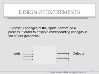
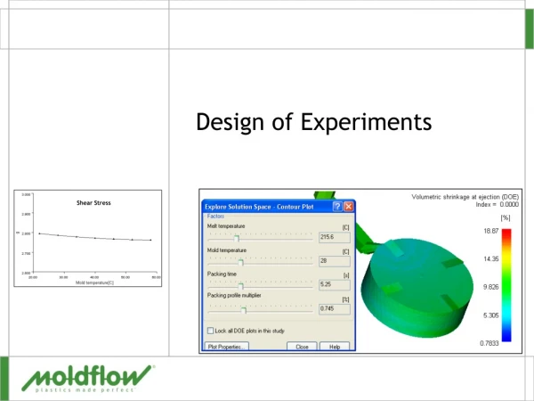
Workshop Design of Experiments. Design Exploration. Workshop. Goal Showing Design Exploration DOE scenario, and creating response charts Model Description The boundary conditions have been applied as shown here. Model is created in Design Modeler Input parameters

Workshop Design of Experiments
E N D
Presentation Transcript
WorkshopDesign of Experiments Design Exploration
Workshop • Goal • Showing Design Exploration DOE scenario, and creating response charts • Model Description • The boundary conditions have been applied as shown here. • Model is created in Design Modeler • Input parameters • ds_cutout – geometry parameter from DM • Bearing load • Output parameters • Mass • Equivalent stress • Total deformation ds_cutout
Workshop 1. File>Open>Link1.dsdb 1 2. Verify all your input and output parameters by double click on parameters set. 2 Input parameters Output parameters 3 3. Return to the Project
Workshop 4. Double click on “Response Surface” to start DOE study 4 5. Double click on DOE Outline of DOE shows input and output parameters 5
Workshop 6. Highlight parameter in “Outline of Design of Experiments” 6 7. In Properties of define type of the design variable and also set up lower and upper bounds. Ds-cutout, continues variable bounds from 4.5-5-5.5 7 8. Bearing load, continues variable bounds from 9-10-11 8
Workshop 9. Highlight DOE -DOE type is set to Central Composite Design by default 9 10 10. Preview and Update design points 11 11. Click on Show Progress to expand Status bar
Workshop Table of DOE shows 9 design points 13 12 13. Select to show Total deformation vs Design Points 12. Click on Design Points vs Parameter
Workshop 14 14. Return to Project Page 15. Double click on Response Surface 16. Update Response Surface 15 17. Double click on Response 17 16
Workshop 18. Set Mode to 2D and X and Y axis as shown 18 19. Switch Mode to 3D and Set X, Y, and Z axis as shown 19
Workshop 20. Click on spider and local sensitivities to plot charts 20
Workshop 21. RMB on the Response surface Insert as Response Point 21 22. RMB on desired Response point and Insert it as Design Point 22 Your Response point should not be the same as one shown here
Workshop 23. Return to Project Page 23 24. Double click on Parameter set 25. Update all design points 24 25 26. RMB on DP1 and Copy inputs to current and Updated selected Design Point 26 27. Return to Project Page 27
Workshop 28. Double click on Solution 28 Check the results in Mechanical