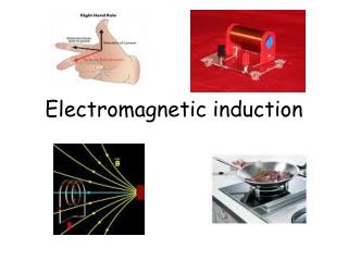
Electromagnetic Induction
Chapter 25. Electromagnetic Induction. Induction. A loop of wire is connected to a sensitive ammeter When a magnet is moved toward the loop, the ammeter deflects. Induction. An induced current is produced by a changing magnetic field

Electromagnetic Induction
E N D
Presentation Transcript
Chapter 25 Electromagnetic Induction
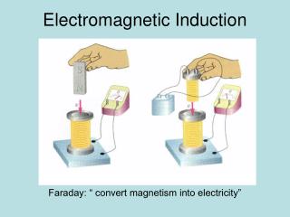
Induction • A loop of wire is connected to a sensitive ammeter • When a magnet is moved toward the loop, the ammeter deflects
Induction • An induced current is produced by a changing magnetic field • There is an induced emf associated with the induced current • A current can be produced without a battery present in the circuit • Faraday’s law of induction describes the induced emf
Induction • When the magnet is held stationary, there is no deflection of the ammeter • Therefore, there is no induced current • Even though the magnet is in the loop
Induction • The magnet is moved away from the loop • The ammeter deflects in the opposite direction
Induction • The ammeter deflects when the magnet ismoving toward or awayfrom the loop • The ammeter also deflects when the loop is moved toward or away from the magnet • Therefore, the loop detects that the magnet is moving relative to it • We relate this detection to a change in the magnetic field • This is the induced current that is produced by an induced emf
Faraday’s law • Faraday’s law of induction states that “the emf induced in a circuit is directly proportional to the time rate of change of the magnetic flux through the circuit” • Mathematically,
Magnetic Flux • Definition: • Magnetic flux is the product of the magnitude of the magnetic field and the surface area, A, perpendicular to the field • ΦB = BA • The field lines may make some angle θwith the perpendicular to the surface • Then ΦB = BA cos θ normal
Faraday’s law • Faraday’s law of induction states that “the emf induced in a circuit is directly proportional to the time rate of change of the magnetic flux through the circuit” • Mathematically,
Faraday’s law • Assume a loop enclosing an area A lies in a uniform magnetic field B • The magnetic flux through the loop is FB = BA cos q • The induced emf is • Ways of inducing emf: • The magnitude of B can change with time • The area A enclosed by the loop can change with time • The angle q can change with time • Any combination of the above can occur
Motional emf • A motional emf is the emf induced in a conductor moving through a constant magnetic field • The electrons in the conductor experience a force, FB = qvB that is directed along ℓ
Motional emf • FB = qvB • Under the influence of the force, the electrons move to the lower end of the conductor and accumulate there • As a result, an electric field E is produced inside the conductor • The charges accumulate at both ends of the conductor until they are in equilibrium with regard to the electric and magnetic forces • qE = qvB or E = vB
Motional emf • E = vB • A potential difference is maintained between the ends of the conductor as long as the conductor continues to move through the uniform magnetic field • If the direction of the motion is reversed, the polarity of the potential difference is also reversed
Example: Sliding Conducting Bar • The induced emf is
Lenz’s law • Faraday’s law indicates that the induced emf and the change in flux have opposite algebraic signs • This has a physical interpretation that is known as Lenz’s law • Lenz’s law: the induced current in a loop is in the direction that creates a magnetic field that opposes the change in magnetic flux through the area enclosed by the loop • The induced current tends to keep the original magnetic flux through the circuit from changing
Lenz’s law • Lenz’s law: the induced current in a loop is in the direction that creates a magnetic field that opposes the change in magnetic flux through the area enclosed by the loop • The induced current tends to keep the original magnetic flux through the circuit from changing B increases with time B decreases with time
Example A single-turn, circular loop of radius R is coaxial with a long solenoid of radius r and length ℓ and having Nturns. The variable resistor is changed so that the solenoid current decreases linearly from I1 to I2in an interval Δt. Find the induced emf in the loop.
Inductance • L is a constant of proportionality called the inductance of the coil and it depends on the geometry of the coil and other physical characteristics • The SI unit of inductance is the henry (H) • Named for Joseph Henry
Inductor • A circuit element that has a large self-inductance is called an inductor • The circuit symbol is • We assume the self-inductance of the rest of the circuit is negligible compared to the inductor • However, even without a coil, a circuit will have some self-inductance Flux through solenoid Flux through the loop
The effect of Inductor • The inductance results in a back emf • Therefore, the inductor in a circuit opposes changes in current in that circuit
RL circuit • An RL circuit contains an inductor and a resistor • When the switch is closed (at time t = 0), the current begins to increase • At the same time, a back emf is induced in the inductor that opposes the original increasing current
Chapter 25 Electromagnetic Waves
Plane Electromagnetic Waves • Assume EM wave that travel in x-direction • Then Electric and Magnetic Fields are orthogonal to x
Plane Electromagnetic Waves EandBvary sinusoidally withx
The EM spectrum • Note the overlap between different types of waves • Visible light is a small portion of the spectrum • Types are distinguished by frequency or wavelength