Download
1 / 37
370 likes | 435 Views
Learn about Infinite Impulse Response (IIR) filter implementation methods, including rational Z transfer functions and linear difference equations. Explore synthesis techniques, characteristics of Butterworth, Chebyshev, and Elliptic filters, and the impact on group delay. Discover key concepts such as zero-pole analysis and frequency behavior in a digital signal processing context.

E N D
DSP C5000 Chapter 15 Infinite Impulse Response (IIR) Filter Implementation
IIR Filters • Rational Z transfer function • Linear difference equation
IIR Filters – Poles and Zeros • Roots of the numerator • Roots of the denominator riare the roots of the z polynomial with bi coefficients. H(z) is null when z is equal to one of the values. They are called the zeroes of the filter and often noted by zi . riare the roots of the z polynomial with ai coefficients.H(z) tends to infinity when z is close to one of these values. They are called the poles of the filters and often noted by pi .
Z Transfer Function • Define frequency behaviour of the filter • Consider a first order z rational filter: magnitude phase H(z) can be evaluated for each value wn from 0 to 1 with 1 corres- ponding to sampling frequency
Z Transfer Function • We obtain the transfer function by evaluation of the z transform on the unit circle • We can see that it is a minimum phase filter (the phase comes back at 0 at Fe/2) because the zero of the filter is inside the unit circle.
Z Transfer Function • If we change the zero z1to 1/ z1 we get the same magnitude transfer function (up to a scale factor) … • But a maximum phase filter (the phase goes to -p at Fe/2) because now, the zero lies outside the unit circle.
IIR Filter Synthesis • Starting from frequency specifications (here low pass filter): • Fpass: passband end frequency, • Fstop: stopband start frequency, • Apass: maximum passband ripple, • Astop: minimum stopband attenuation.
IIR Filters Synthesis • Analog prototype with analog to digital transformation (bilinear transform) : • Digital to analog frequency specification transformation using prewarping • Analog filter prototype • Analog transfer function to digital transfer function transformation using bilinear transform. • Direct digital method : Yule Walker • Try to find the recursive filter of order N which is as close as possible to the frequency specifi-cations using the least square optimization method.
IIR Filters Synthesis • Bilinear transform : • One to one map of analog frquencies to digital frequencies. • Based on the approximation of the continuous integral operator by the trapezoïdal method. Z transform Laplace transform Equating integral operators, we get the bilinear transform.
IIR Filters Synthesis • Bilinear transform • Maps the stability region of the Laplace plane inside the unit circle of the complex plane
IIR Filters Synthesis • Bilinear transform : The one to one mapping achieved by this transform prevents aliasing.
IIR Filters Synthesis • Characteristics frequencies (Fp, Fa) of the target specifications have to be warped. • This warped specifications is used to compute an analog prototype using approximation functions : • Butterworth • Chebyshev I • Chebyshev II • Elliptic • Then the analog prototype is tranformed into a digital filter that matches target frequency specification thanks to Bilinear Transform (BT) (this cancels the warping introduce at the first step).
IIR Characteristics • Butterworth filters : • Defined by its order N and its cut-off frequency fp. • Monotonic magnitude transfer function. • Matlab commands: • buttord : estimate the needed order • butter : compute the digital filter from • analog prototype using warping and BT, • given the order and cut-off frequency. • Sample Matlab code
IIR Characteristics • Chebyshev I filters : • Defined by its order N, its passband corner • frequency fpand its passband ripple e. • Ripple in passband and monotonic in stopband. • Matlab commands: • cheb1ord : estimate the needed order • cheby1 : compute the digital filter from • analog prototype using warping and BT, • Given the order and passband ripple and • Corner frequency. • Sample Matlab code TN( ) is a Chebyshev polynomial of order N
IIR Characteristics • Chebyshev II filters : • Defined by its order N, its stopband edge • frequency fsand its stopband attenuation e. • Monotonic in passband and ripple in stopband. • Matlab commands: • cheb2ord : estimate the needed order • cheby2 : compute the digital filter from • analog prototype using warping and BT, • Given the order and stopband attenuation • and edge frequency. • Sample Matlab code TN( ) is a Chebyshev polynomial of order N
IIR Characteristics • Elliptic filters : • Defined by its order N, its passband and stopband • edge frequencies, fp and fs, its passband ripple and • its stopband attenuation e. • Ripple in passband and in stopband. • Matlab commands: • ellipord : estimate the needed order • ellip : compute the digital filter from • analog prototype using warping and BT, • given the order, passband ripple, stopband • attenuation and center frequency. • Sample Matlab code RN( ) is a Chebyshev rationnal polynomial of order N
IIR Characteristics • Group delay • Characterize the phase distorsion (waveform distorsion) introduced by the filter.
z-1 z-1 z-1 z-1 z-1 z-1 z-1 z-1 IIR structure • Derived from difference equation Direct form I b0 xn yn b1 -a1 -a2 b2 • non canonical form -a3 b3 bQ-1 -aQ-1
z-1 z-1 z-1 z-1 IIR structure Direct form II b0 xn yn -a1 b1 -a2 b2 • Canonical form -a3 b3 -aQ-1 bQ-1
z-1 z-1 z-1 z-1 IIR structure Transposed direct form II b2 xn yn b1 -a1 • Canonical form -a2 b2 b3 -a3 bQ-1 -aQ-1
IIR – Coefficients quantization • Finite precision of DSP involves coefficients quantization: • Let consider the denominator of the transfer function with , the kth quantized coefficients and Dak the quantification error. Quantized denominator is then: • The resulting quantified poles will disrupt the transfer function. • The higher order the polynomial is, the greater will be pertubation on its roots due to quantization. • Following slides illustrate this fact: • Next slide shows the transfer function of a 6th order direct form filter for different quantification. • Following one shows the transfer function obtained for the same filter and same quantificaiton, but with a cascade structure of second order section, this last structure is much less sensitive to quantization than the previous one.
IIR structure • This sensitivity to coefficients quantization leads to second order cascade or parallel form. • Second order section is chosen to get the least order together with complex conjugated roots. 4th order example: Parallel form Cascade form c0 yn xn xn yn Spectral factorisation Partial fraction expansion
IIR – Cascade structure • Cascade structure involves addressing two problems : • Pairing: which zeros with which poles to form a second order rational transfer function. The goal will be minimize the overshoot caused by the poles. • Ordering: which second order section will be ahead and which one will be the last. To answer to this question we will have consider quantification noise and the way to minimize it.
IIR – case study 1 • Consider the following specification: • Using inverse Chebyshev approximation, we get a 6th order filter (matlab commands) [N,Wn]=CHEB2ORD(1800/8000,4000/8000,0.01,50); [B,A]=CHEBY2(N,50,Wn)
IIR – case study 2 Actual transfer function is obtained with: freqz(B,A) Plot of poles and zeros with: zplane(A,B) 3 2 1 Pairing: complex conjugate poles closest to the unit circle (responsible for the greatest overshoot) are paired with complex conjugate zeros closest in frequency (angle on unit circle). Then the process iterate with the next complex conjugate closest to the unit circle. This done with the following routine
z-1 z-1 z-1 z-1 IIR – data quantization For DSP, quantification noise appear when we truncate the accumulator to store its high part. (en equivalent noise source) Direct form II one noise source Transposed direct form II two noise sources en en b0 b2 xn yn xn yn -a1 b1 b1 -a1 -a2 b2 -a2 b2 Output noise power is reduced by the ENB of the complete filter Output noise power is only reduced by the ENB of the denominator
z-1 z-1 z-1 z-1 IIR – scaling factor • Direct form II To prevent overflow when storing at the node wn, we need a scale factor to have a 0 dB gain from input to this node. This scale factor, a, is commonly computed depending on the nature of signal that will be process: Narrow band signal, in this case we use L norm and we get: Wide band signal, we use L2norm and we get: Futhermore we have: wn b0 xn yn -a1 b1 -a2 b2 a b0 /a wn 1/a xn yn b1 /a -a1 -a2 b2 /a
IIR – ordering • Depend on: • Criteria for scale factor computation, Lor L2 norm. • Which norm of the quantization noise we want to minimize L(max value) or L2 norm (power). • Following rules could apply: • L for scale factor and L2 for noise ascending order of overshoot. • L2for scale factor and L for noise descending order of overshoot. If the same norm is used no prefered order.
Scale factor & ordering • 6th filter example (look at this routine) : quantization noise source
IIR – coefficients coding • We have to choose the right Qn coding for the coefficients. • For second order section, A(z) or B(z) can be written, if we let their roots to be • Denominator: for stability we need |r|<1, so coefficients belong to [-2,2]. • Numerator, by using analog approximation function as prototype we get zeros on the unit circle so |r|=1 and coefficients also belong to [-2,2]. • The right coding is then Q14 for 16 bits word. • Look at this routine which does the work fir the 6th order filter.
IIR – noise power • The noise power at the output of that 6th order filter: First stage noise power Second stage noise power Third stage noise power • Input scale factor attenuates only the input signal not the quantization noise: • the lower the scale factor is the worst the signal to noise ratio will be.
IIR - computation • Evaluation of an order 2 direct form II is as follows: ACC=x(n) a0 ACC=ACC - a1 w(n-1) ACC=ACC - a2 w(n-2) ACC<<2 w(n)=ACCH ACC=w(n) b0 ACC=ACC + b2 w(n-2) ACC=ACC + b1 w(n-1) ACC<<2 y(n)=ACCH Q29=Q15 Q14 Q29=Q29 - (Q15 Q14) Q29=Q29 - (Q15 Q14) Q31=Q29 22 Q15 Q29=Q15 Q14 Q29=Q29 + (Q15 Q14) Q29=Q29 + (Q15 Q14) Q31=Q29 22 Q15 w(n-2)=w(n-1) w(n-1)=w(n)
a w2(n-1) w1(n-2) w1(n-1) w2(n-2) b21 b22 b20 b11 b12 b10 a21 a11 a12 a22 IIR – program on C54 • Following program works on a sample by sample basis and is C callable. Memory managment *AR3 memfilt *AR2 sect1
Follow on Activities for thr C5416 DSK • Laboratory 6 for the C5416 DSK • Implemements high pass and low pass Butterworth filters from 1st order to 6th order. • Laboratory 7 for the C5416 DSK • Implemements band stop and notch filters using poles / zeroes and Bilinear Transform (BLT). • Laboratory 8 for the C5416 DSK • Looks at sharpness of cut off and stability of IIR filters designed by placing poles and zeroes and Bilinear Transform (BLT).
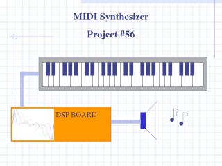
Follow on Activities for thr C5510 DSK • Application 3 for the C5510 DSK • Uses IIR filter for reverberation • Simulates single and multiple reflections from the walls of a room. Introduces the configuration used for an Infinite Impulse Response (IIR) filter. • The majority of the code is written in C, except where the C code would be too slow and assembly code is required