Download
1 / 15
150 likes | 293 Views
Liquid Crystal Elastomer Response to Light. Rafael Soares Zola CPIP-LCI Advisor: Peter Palffy-Muhoray. Objectives . Observe the response of the Liquid Crystal Elastomer (LCE) to a source of light; Understand the key features of the Spatial Light Modulator (SLM);

E N D
Liquid Crystal Elastomer Response to Light Rafael Soares Zola CPIP-LCI Advisor: Peter Palffy-Muhoray
Objectives • Observe the response of the Liquid Crystal Elastomer (LCE) to a source of light; • Understand the key features of the Spatial Light Modulator (SLM); • Use the SLM as a dynamic element; • Apply light with intensity varying with position and time on the sample;
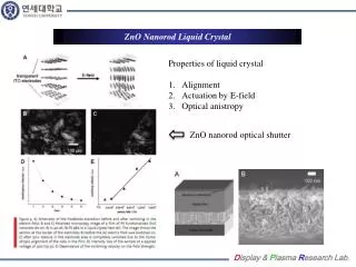
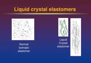
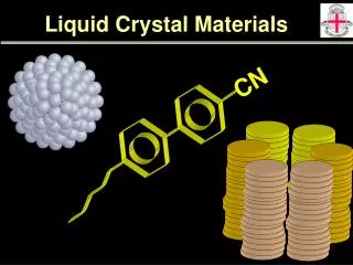
4.0mm 7.5mm Background • Liquid Crystal Elastomer*: Rubber and Liquid Crystal! Doped Cross-Linker (12%) Mesogen Backbone azo dye Disperse Orange III *M. Camacho-Lopez, et al Nature Materials 3, 307 (2004).
Background • Change in the degree of order: • cis-trans transition (Azo Dye) • temperature • The free energy of the elastomer coupling term liquid crystal rubber
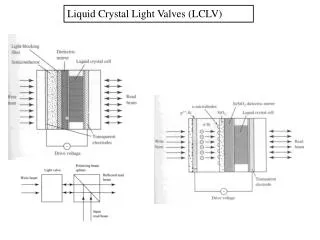
Background • SLM: Twisted Nematic cell used as dynamic element in experimental setups
Background Transmissive SLM Number of pixels:832 x 624 Pixel pitch: 32m Image frame rate: max. 60Hz Active area: 26.6mm x 20.0mm Laser through Computer Image
Background • Intensity vs. gray level:
Analyzer Lens Polarizer Mirror Argon Laser - CW - =514nm Camera Sample Filter 514nm Computer Setup
Setup Microscope Objective SLM Camera Sample
Results Ppump=15mW
Results Ppump=15mW ttransition= 10s
Results Ppump=43.73mW ttransition= 10s
Conclusions • The SLM can be used to control the intensity over the sample spatially and temporally • This control allows one to move the LCE in some specific manner • Coordinated movements depends on accurate control of the beam over the sample
Acknowledgements Especial Thanks for: Dr. Michele Moreira (muito obrigado mesmo!!) Jake Fontana Jeremy Neal