Download
1 / 27
270 likes | 514 Views
Space-Charge Effects in RF Photoinjectors. Bruce Carlsten Los Alamos National Laboratory April 18, 2013. Space charge in photoinjectors. High brightness electron beams belong to a significantly different space-charge community (but with many shared concepts and terms)

E N D
Space-Charge Effects in RF Photoinjectors Bruce Carlsten Los Alamos National Laboratory April 18, 2013
Space charge in photoinjectors High brightness electron beams belong to a significantly different space-charge community (but with many shared concepts and terms) • Beams in RF photoinjectors are highly space-charge dominated and very quasi-laminar, and never reach a stationary state • We care about emittance growth in this regime which will dominate beam evolution as the beam gets accelerated and enters the emittance-dominated regime • The emittance growth arises from space-charge nonlinearities from both time-dependent (axial) and radial nonuniformities • Much of the emittance growth is reversible – our modeling is actually very accurate (IMPACT, OPAL, PARMELA, others) I’ll mostly be talking about projected rmsemittances instead of slice rmsemittances although slice emittances dictate FEL performance
Outline • Description of RF photoinjectors • Basic space-charge induced emittance growth • Transverse plasma oscillations and emittance oscillations • Comparison to DC beams and radial nonuniformities • Dominant mechanisms for final emittance Wavebreaking Landau damping of emittance oscillations • Other space-charge comments I would like to acknowledge important contributions and slides from Dinh Nguyen and Steve Russell
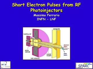
Modelocked Drive Laser Schematic of an RF Photoinjector Klystron Master Oscillator X Solenoid Bucking Coil UV laser beam Electron beam Injector cavity (n+½ cells) Photocathode (Cu, Cs2Te, etc.)
SLAC Boeing BNL LANL – AFEL BNL/UCLA/SLAC BNL/KEK/SHI BNL/UCLA/SLAC LANL - APEX Normalized emittance for 1 nC has been reduced from tens of mm to 1 mm LCLS scaling: PITZ scaling:
APEX photoinjector performance • 5 ½ cell, 1300 MHz standing wave structure. • Output energy: 7 – 8 MeV • Charge/bunch 10 nC • Normalized emittance (10 ps beam): 2.5 mm at 1 nC/bunch 8 mm at 5 nC/bunch • Electron bunch length: 20 ps FWHM compressed to less than 1 ps FWHM with magnetic bunching.
Solenoids Magnetic field Vacuum plenum Resonant cavities Electric field 3-cell Injector Cathode Beam Aperture Typical cavity designelectric and magnetic field distribution
- + - + - + - + z - + - + - + - + - + 1st half-cell 2nd full-cell 3rd full-cell Snapshots of axial electric and magnetic fields: 30o phase Axial magnetic field Axial electric field Longitudinal force Image charge t = p/6 Vacuum Cathode Transverse force Highly nonlinear radial space-charge force
Snapshots of axial electric and magnetic fields: 60o phase Axial magnetic field Axial electric field t = p/3 Example: Electron bunch length z 1st half-cell 2nd full-cell 3rd full-cell
Snapshots of axial electric and magnetic fields: 90o phase Axial magnetic field Axial electric field Longitudinal force t = p/2 Lab frame r z z Transverse forces lz Bunch rest frame 1st half-cell 2nd full-cell 3rd full-cell glz
Snapshots of axial electric and magnetic fields: 120o phase Axial magnetic field Axial electric field t = 2p/3 Fields in rest frame Er Ez z glz 1st half-cell 2nd full-cell 3rd full-cell
K-J Kim integrated motion in photoinjector to estimate emittance growth These expressions are for the emittance due to time-varying (axial variations) in RF forces, space-charge forces and dominate the initial emittance growth:
Injector only Injector + boosters + solenoid Boosters Solenoid Emittance oscillations in nominal RF gun design (700 MHz, 3 nC, 9 ps) We don’t have time to talk about the double minimum or why the strategy is catch the beam at the peak between them Adding booster linacs and a second solenoid allows different phase-space envelopes to realign at higher energy, resulting in a lower beam emittance
The emittance reduction is known as emittance compensation center Space charge causes phase space ellipses to fan out, thus large projected emittance Initially all phase space ellipses are aligned head tail Electron bunch is sliced into N axial slices, each having its own phase space ellipse Different phase space ellipses realigned to yield small projected emittance Magnetic solenoid acts like a lens, flipping the phase space ellipses
Emittance compensation modeling for a drifting slug of charge
Emittance oscillations results from plasma oscillations Bow-tie phase space distribution forms during the plasma oscillations of particles with different equilibrium radii
To first order, plasma oscillations all have the same period The transverse motion of a particle in a slice of the beam in a uniform focusing channel of normalized strength K is given by (nonaccelerating) The equilibrium particle radius (no acceleration) is given by We write the particle radius as If the beam is rms matched and the density nonuniformity is small, we get this equation:
Nonlinear radial forces in diodes lead to radial oscillations in DC beams with the same basic physics r r’ r r Nonlinear density and curvature lead to radial plasma oscillations - nonlinear potential energy effect and emittance oscillations Also see beginnings of wavebreaking in phase space (means distribution becomes multi-valued in r)
Nominal simulation - 4 kA, 4 MeV showing emittance oscillations: Early emittance oscillations with all particles in phase Final thermalized emittance, can estimate from the initial nonlinear free energy Initial radial current distribution Final phase space distribution - kinks approximate final ellipse after long thermalizational Thermalization arises from either spread in radial oscillation frequencies (Landau damping) or wavebreaking (which is suppressed in this simulation)
Wave breaking dominates final emittance for both RF photoinjectors and long DC beams If no wave breaking occurs (in phase space), plasma oscillations will persist for very long distances before thermalization. However, if the beam wave breaks, thermalization will occur much faster with a charateristic distance of a ¼ betatron period. Large scale wave breaking (say of ½ the particles) will occur for a uniform density beam with an initial emittance exceeding If this happens, the initial emittance is frozen; if only a few particles wave break, they can lead to a much smaller final emittance. High-current, high-brightness electron beams are under this limit, and do not undergo immediate, large-scale wave breaking. However, particles with low enough density and large enough radial position will always wave break.
Wave breaking in an RF photoinjector Large-scale wavebreaking can occur for radially nonuniform distributions: Uniform case - bowtie distribution results from spread in plasma frequencies Nonuniform case - horizontal component from wavebreaking - final emittance is 4 times larger
PITZ photoinjector is current state-of-the-art PITZ scaling:
MaRIE XFEL photoinjector design Scaled PITZ geometry (2.856 GHz), optimization of magnetic field profile allows better emittance compensation (2-way), lower amounts of wave breaking Emittance predicted to be ~ 0.1 mm for 100 pC (OPAL) Dominated by radial nonlinearities (not slice fanning) with a minor amount of wavebreaking
MaRIE XFEL photoinjector design Slice emittance Longitudinal phase space Current profile Beams from both RF photoinjectors and DC photo-guns (Cornell) are now reaching the thermal limits)
Longitudinal phase space • 1. Energy spread from potential depression: • MaRIEphotoinjector beam is very cold, with a slice RMS energy spread of about a couple hundred eV. Surprisingly, that’s still above the value you’d expect from the beam’s own potential depression which for 10 A is only about 25 eV. • The minimum longitudinal emittance for a charge Q is • which would be about 1.5 microns for a charge of 1 nC; MaRIEphotoinjector design also well above that
Summary RF photoinjectors are becoming a mature technology. We understand the limits of transverse emittance and are beginning to reach them (in the sense the beam is beginning to be dominated by thermal effects in modern designs). We are simultaneously compensating transverse and axial space-charge nonlinearities; residual non-thermal emittance is typically from wave-breaking due to radial effects. Modeling photoinjectors is hard – wide range of rest frames as the beam is initiated, scattering off grid leads to artificial wave breaking Our understanding of space-charge effects on the beam’s longitudinal emittance is still immature and we should see factors of 4 or more improvements in the future. Emittance partitioning will require even greater modeling accuracy, especially for 3-D geometries. There is still a lot of work to do to understand and model coherent synchrotron radiation effects.