Understanding Thermal Radiation: Emission, Absorption, and Properties of Matter
310 likes | 469 Views
This module explores the principles of thermal radiation and energy transfer as a result of molecular and atomic movements. It delves into the emission of thermal energy by matter, governed by the Stefan-Boltzmann law and Planck's distribution, covering electromagnetic waves in a vacuum. Key concepts include surface emissivity, the relationship between absorptivity and emissivity, and the characteristics of real versus ideal surfaces. The module also addresses practical applications of these principles in engineering and environmental science.

Understanding Thermal Radiation: Emission, Absorption, and Properties of Matter
E N D
Presentation Transcript
MODULE 9 Radiation Heat Transfer
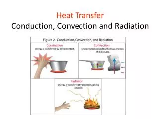
Thermal energy emitted by matter as a result of vibrational and rotational movements of molecules, atoms and electrons. The energy is transported by electromagnetic waves (or photons). Radiation requires no medium for its propagation, therefore, can take place also in vacuum. All matters emit radiation as long as they have a finite (greater than absolute zero) temperature. The rate at which radiation energy is emitted is usually quantified by the modified Stefan-Bolzmann law: where the emissivity, e , is a property of the surface characterizing how effectively the surface radiates compared to a "blackbody" (0<e<1 ). E=q/A (W/m2) is the surface emissive power. s is the Stefan-Boltzmann constant (s=5.67x10⁻⁸ W/(m2K4)). Tb is the absolute surface temp. (in K) EA = q=dQ/dt=eTb4
Electromagnetic radiation spectrum Thermal radiation spectrum range: 0.1 to 100 mm It includes some ultraviolet (UV) radiation and all visible (0.4-0.76 mm) and infrared radiation (IR). Wavelength, , m
The Planck Distribution The Planck law describes theoretical spectral distribution for the emissive power of a black body. It can be written as where C1=3.742x10⁸ (W.mm4/m2) and C2=1.439x10⁴ (mm.K) are two constants. The Planck distribution is shown in the following figure as a function of wavelength for different body temperatures.
Planck Distribution • At given wavelength, the emissive power increases with increasing temperature • As the temperature increases,more emissive energy appear at shorter wavelengths • For low temperature (>800 K), all radiant energy falls in the infrared region and is not visible to the human eyes. That is why only very high temperature objects, such as molten iron, can glow. • Sun can be approximated as a blackbody at 5800 K
A = r2·dΩ r L = r·α α L Angles and Arc Length We are well accustomed to thinking of an angle as a two dimensional object. It may be used to find an arc length: Solid Angle We generalize the idea of an angle and an arc length to three dimensions and define a solid angle, Ω, which like the standard angle has no dimensions. The solid angle, when multiplied by the radius squared will have dimensions of length squared, or area, and will have the magnitude of the encompassed area.
θ dA1 dA1·cosθ Projected Area The area, dA1, as seen from the prospective of a viewer, situated at an angle θ from the normal to the surface, will appear somewhat smaller, as cos θ·dA1. This smaller area is termed the projected area. Aprojected = cos θ·Anormal Intensity The ideal intensity, Ib, may now be defined as the energy emitted from an ideal body, per unit projected area, per unit time, per unit solid angle.
Spherical Geometry Since any surface will emit radiation outward in all directions above the surface, the spherical coordinate system provides a convenient tool for analysis. The three basic coordinates shown are R, φ, and θ, representing the radial, azimuthal and zenith directions. In general dA1 will correspond to the emitting surface or the source. The surface dA2 will correspond to the receiving surface or the target. Note that the area proscribed on the hemisphere, dA2, may be written as: dA2 dA1 R·sin θ Recalling the definition of the solid angle, dA = R2·dΩ we find that: dΩ = R2·sin θ·dθ·dφ θ R Δφ φ
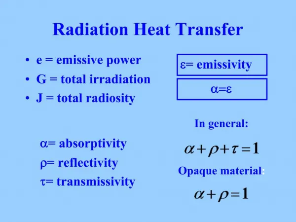
Reflected Radiation Absorbed Radiation Transmitted Radiation Real Surfaces Thus far we have spoken of ideal surfaces, i.e. those that emit energy according to the Stefan-Boltzman law: Eb = σ·Tabs4 Real surfaces have emissive powers, E, which are somewhat less than that obtained theoretically by Boltzman. To account for this reduction, we introduce the emissivity, ε. Emissive power from any real surface is given by: E = ε·σ·Tabs4 • Receiving Properties • Targets receive radiation in one of three ways; they absorption, reflection or transmission. • ·Absorptivity, α, the fraction of incident radiation absorbed. • ·Reflectivity, ρ, the fraction of incident radiation reflected. • Transmissivity, τ, the fraction of incident radiation transmitted. Incident Radiation, G
Surface A, TA Surface B, TB We see, from Conservation of Energy, that: α + ρ + τ = 1 In this course, we will deal with only opaque surfaces, τ = 0, so that: α + ρ = 1 Relationship Between Absorptivity,α, and Emissivity,ε Consider two flat, infinite planes, surface A and surface B, both emitting radiation toward one another. Surface B is assumed to be an ideal emitter, i.e. εB = 1.0. Surface A will emit radiation according to the Stefan-Boltzman law as: EA = εA·σ·TA4 and will receive radiation as: GA = αA·σ·TB4 The net heat flow from surface A will be: q΄΄ = εA·σ·TA4 - αA·σ·TB4 Now suppose that the two surfaces are at exactly the same temperature. The heat flow must be zero according to the 2nd law. If follows then that: αA = εA
Thermodynamic properties of the material, α and ε may depend on temperature. In general, this will be the case as radiative properties will depend on wavelength, λ. The wave length of radiation will, in turn, depend on the temperature of the source of radiation. The emissivity, ε, of surface A will depend on the material of which surface A is composed, i.e. aluminum, brass, steel, etc. and on the temperature of surface A. The absorptivity, α, of surface A will depend on the material of which surface A is composed, i.e. aluminum, brass, steel, etc. and on the temperature of surface B. Black Surfaces Within the visual band of radiation, any material, which absorbs all visible light, appears as black. Extending this concept to the much broader thermal band, we speak of surfaces with α = 1 as also being “black” or “thermally black”. It follows that for such a surface, ε = 1 and the surface will behave as an ideal emitter. The terms ideal surface and black surface are used interchangeably.
Diffuse Surface: Refers to directional independence of the intensity associated with emitted,reflected ,or incident radiation. Grey Surface: A surface for which the spectral absorptivity and the emissivity are independent of wavelength over the spectral regions of surface irradiation and emission.
Relationship Between Emissive Power and Intensity By definition of the two terms, emissive power for an ideal surface, Eb, and intensity for an ideal surface, Ib. Replacing the solid angle by its equivalent in spherical angles: Integrate once, holding Ib constant: Integrate a second time. (Note that the derivative of sin θ is cos θ·dθ.) Eb = π·Ib
dA2 dA2·cos θ2 R Next we will project the receiving surface onto the hemisphere surrounding the source. First find the projected area of surface dA2, dA2·cos θ2. (θ2 is the angle between the normal to surface 2 and the position vector, R.) Then find the solid angle, Ω, which encompasses this area. To obtain the entire heat transferred from a finite area, dA1, to a finite area, dA2, we integrate over both surfaces:
θj D dr dAj Aj θi L dAi R R dAi Total energy emitted from surface 1: qemitted = E1·A1 = π·I1·A1 View Factors-Integral Method Define the view factor, F1-2, as the fraction of energy emitted from surface 1, which directly strikes surface 2. Example Consider a diffuse circular disk of diameter D and area Aj and a plane diffuse surface of area Ai << Aj. The surfaces are parallel, and Ai is located at a distance L from the center of Aj. Obtain an expression for the view factor Fij.
Since dA1 is a differential area Let ρ2 L2 + r2 = R2. Then 2·ρ·dρ = 2·r·dr.
1 2 Enclosures In order that we might apply conservation of energy to the radiation process, we must account for all energy leaving a surface. We imagine that the surrounding surfaces act as an enclosure about the heat source which receive all emitted energy. For an N surfaced enclosure, we can then see that: This relationship is known as the Conservation Rule”. This relationship is known as “Reciprocity”. Reciprocity Example: Consider two concentric spheres shown to the right. All radiation leaving the outside of surface 1 will strike surface 2. Part of the radiant energy leaving the inside surface of object 2 will strike surface 1, part will return to surface 2. Find F2,1 . Apply reciprocity.
ε·Eb ρ·G G i j k Associative Rule Consider the set of surfaces shown to the right: Clearly, from conservation of energy, the fraction of energy leaving surface i and striking the combined surface j+k will equal the fraction of energy emitted from i and striking j plus the fraction leaving surface i and striking k. This relationship is known as the “Associative Rule”. Radiosity Radiosity, J, is defined as the total energy leaving a surface per unit area and per unit time. J ≡ ε·Eb + ρ·G
Jj Ji Net Exchange Between Surfaces Consider the two surfaces shown. Radiation will travel from surface i to surface j and will also travel from j to i. qi→j = Ji·Ai· Fi→j likewise, qj→i = Jj·Aj· Fj→j The net heat transfer is then: qj→i (net) = Ji·Ai· Fi→j - Jj·Aj· Fj→j From reciprocity we note that F1→2·A1 = F2→1·A2 so that qj→i (net) = Ji·Ai· Fi→j - Jj· Ai· Fi→j = Ai· Fi→j·(Ji – Jj)
Net Energy Leaving a Surface The net energy leaving a surface will be the difference between the energy leaving a surface and the energy received by a surface: q1→ = [ε·Eb – α·G]·A1 Combine this relationship with the definition of Radiosity to eliminate G. J ≡ ε·Eb + ρ·G G = [J - ε·Eb]/ρ q1→ = {ε·Eb – α·[J - ε·Eb]/ρ}·A1 Assume opaque surfaces so that α + ρ = 1 ρ = 1 – α, and substitute for ρ. q1→ = {ε·Eb – α·[J - ε·Eb]/(1 – α)}·A1 Put the equation over a common denominator: assume that α = ε
Electrical Analogy for Radiation We may develop an electrical analogy for radiation, similar to that produced for conduction. The two analogies should not be mixed: they have different dimensions on the potential differences, resistance and current flows.
· Insulated surfaces. In steady state heat transfer, a surface cannot receive net energy if it is insulated. Because the energy cannot be stored by a surface in steady state, all energy must be re-radiated back into the enclosure. Insulated surfaces are often termed as re-radiating surfaces. • · Black surfaces: A black, or ideal surface, will have no surface resistance: • In this case the nodal Radiosity and emissive power will be equal.
(1-1)/(1A1) (1-2)/(2A2) Eb2 T24 R1 R12 R2 Eb1 T14 1/(A1F1→2) J1 J2 1/(A1F1→2) J1 J2 • · Large surfaces: Surfaces having a large surface area will behave as black surfaces, irrespective of the actual surface properties: • Consider the case of an object, 1, placed inside a large enclosure, 2. The system will consist of two objects, so we proceed to construct a circuit with two radiosity nodes. Now we ground both Radiosity nodes through a surface resistance.
1/(A1F1→2) J1 J2 (1-1)/(1A1) Eb1 T14 Eb2 T24 R1 R12 • Since A2 is large, R2 = 0. The view factor, F1→2 = 1 • Sum the series resistances: • RSeries = (1-1)/(1A1) + 1/A1 = 1/(1A1) • Ohm’s law: • i = V/R • or by analogy: • q = Eb/RSeries = 1A1(T14 – T24) • Returning for a moment to the coal grate furnace, let us assume that we know (a) the total heat being produced by the coal bed, (b) the temperatures of the water walls and (c) the temperature of the super heater sections.
Apply Kirchoff’s law about node 1, for the coal bed: • Similarly, for node 2: And for node 3: • The three equations must be solved simultaneously. Since they are each linear in J, matrix methods may be used:
Surface 1: Find the coal bed temperature, given the heat flow: • Surface 2: Find the water wall heat input, given the water wall temperature: • Surface 3: (Similar to surface 2) Find the water wall heat input, given the water wall temperature: