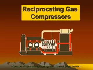
Reciprocating pump
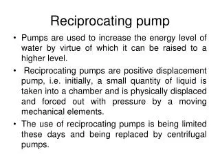
Reciprocating pump. Pumps are used to increase the energy level of water by virtue of which it can be raised to a higher level.

Reciprocating pump
E N D
Presentation Transcript
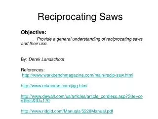
Reciprocating pump Pumps are used to increase the energy level of water by virtue of which it can be raised to a higher level. Reciprocating pumps are positive displacement pump, i.e. initially, a small quantity of liquid is taken into a chamber and is physically displaced and forced out with pressure by a moving mechanical elements. The use of reciprocating pumps is being limited these days and being replaced by centrifugal pumps.
Reciprocating pump For industrial purposes, they have become obsolete due to their high initial and maintenance costs as compared to centrifugal pumps. Small hand operated pumps are still in use that include well pumps, etc. These are also useful where high heads are required with small discharge, as oil drilling operations.
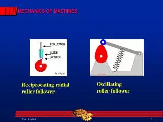
Main components A reciprocation pumps consists of a plunger or a piston that moves forward and backward inside a cylinder with the help of a connecting rod and a crank. The crank is rotated by an external source of power. The cylinder is connected to the sump by a suction pipe and to the delivery tank by a delivery pipe. At the cylinder ends of these pipes, non-return valves are provided. A non-return valve allows the liquid to pass in only one direction. Through suction valve, liquid can only be admitted into the cylinder and through the delivery valve, liquid can only be discharged into the delivery pipe.
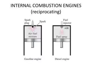
Working of Reciprocating Pump When the piston moves from the left to the right, a suction pressure is produced in the cylinder. If the pump is started for the first time or after a long period, air from the suction pipe is sucked during the suction stroke, while the delivery valve is closed. Liquid rises into the suction pipe by a small height due to atmospheric pressure on the sump liquid. During the delivery stroke, air in the cylinder is pushed out into the delivery pipe by the thrust of the piston, while the suction valve is closed. When all the air from the suction pipe has been exhausted, the liquid from the sump is able to rise and enter the cylinder.
Working of Reciprocating Pump • During the delivery stroke it is displaced into the delivery pipe. Thus the liquid is delivered into the delivery tank intermittently, i.e. during the delivery stroke only.
Classification of Reciprocating pumps Following are the main types of reciprocating pumps: • According to use of piston sides • Single acting Reciprocating Pump: If there is only one suction and one delivery pipe and the liquid is filled only on one side of the piston, it is called a single-acting reciprocating pump. • Double acting Reciprocating Pump: A double-acting reciprocating pump has two suction and two delivery pipes, Liquid is receiving on both sides of the piston in the cylinder and is delivered into the respective delivery pipes.
Classification of Reciprocating pumps • According to number of cylinder Reciprocating pumps having more than one cylinder are called multi-cylinder reciprocating pumps. • Single cylinder pump A single-cylinder pump can be either single or double acting • Double cylinder pump (or two throw pump) A double cylinder or two throw pump consist of two cylinders connected to the same shaft.
Classification of Reciprocating pumps • According to number of cylinder • Triple cylinder pump (three throw pump) A triple-cylinder pump or three throw pump has three cylinders, the cranks of which are set at 1200 to one another. Each cylinder is provided with its own suction pipe delivery pipe and piston. • There can be four-cylinder and five cylinder pumps also, the cranks of which are arranged accordingly.
Classification of Reciprocating pumps • According to number of cylinder
Discharge through a Reciprocating Pump Let A = cross sectional area of cylinder r = crank radius N = rpm of the crank L = stroke length (2r) Discharge through pump per second= Area x stroke length x rpm/60 This will be the discharge when the pump is single acting.
Discharge through a Reciprocating Pump Discharge in case of double acting pump Discharge/Second = Where, Ap = Area of cross-section of piston rod However, if area of the piston rod is neglected Discharge/Second =
Discharge through a Reciprocating Pump • Thus discharge of a double-acting reciprocating pump is twice than that of a single-acting pump. • Owing to leakage losses and time delay in closing the valves, actual discharge Qa usually lesser than the theoretical discharge Qth.
Slip Slip of a reciprocating pump is defined as the difference between the theoretical and the actual discharge. i.e. Slip = Theoretical discharge - Actual discharge = Qth. - Qa Slip can also be expressed in terms of %age and given by
Slip Slip Where Cd is known as co-efficient of discharge and is defined as the ratio of the actual discharge to the theoretical discharge. Cd = Qa / Qth. Value of Cd when expressed in percentage is known as volumetric efficiency of the pump. Its value ranges between 95---98 %. Percentage slip is of the order of 2% for pumps in good conditions.
Negative slip It is not always that the actual discharge is lesser than the theoretical discharge. In case of a reciprocating pump with long suction pipe, short delivery pipe and running at high speed, inertia force in the suction pipe becomes large as compared to the pressure force on the outside of delivery valve. This opens the delivery valve even before the piston has completed its suction stroke. Thus some of the water is pushed into the delivery pipe before the delivery stroke is actually commenced. This way the actual discharge becomes more than the theoretical discharge. Thus co-efficient of discharge increases from one and the slip becomes negative.
Power Input Consider a single acting reciprocating pump. Let hs = Suction head or difference in level between centre line of cylinder and the sump. hd = Delivery head or difference in between centre line of cylinder and the outlet of delivery pipe. Hst = Total static head = hs + hd Theoretical work done by the pump = ρ Qth g Hst
Power Input Power input to the pump However, due to the leakage and frictional losses, actual power input will be more than the theoretical power. Let η = Efficiency of the pump. Then actual power input to the pump
Problem-1: A single-acting reciprocating pump discharge 0.018 m3 /s of water per second when running at 60 rpm. Stroke length is 50 cm and the diameter of the piston is 22 cm. If the total lift is 15 m, determine:a) Theoretical discharge of the pumpb) Slip and percentage slip of the pumpc) Co-efficient of discharged) Power required running the pump Solution: L = 0.5 m Qa = 0.018m3 /s D = 0.22 m N = 60 rpm Hst = 15 m
Problem-1 Solution: (a) Qth = (π/4)x(0.22)2x(0.5x60/60) Qth = 0.019 m3 /s (b)Slip = Qth - Qa Slip = 0.019 – 0.018 = 0.001m3 /s Percentage slip = (Qth - Qa)/ Qth = (0.019-0.018)/0.019 = 0.0526 or 5.26% .
Problem-1 Solution: (c) Cd = Qa / Qth = 0.018/0.019 = 0.947 (d) Power Input = ρ Qth g Hst (Neglecting Losses) = 1000 x 0.019 x 9.81x 15 = 2796 w or 2.796 kW .
Problem-2: A three-throw reciprocating pump delivering 0.1 m3 /s of water against a head of 100 m. Diameter and stroke length of the cylinder are 25 cm and 50 cm respectively. Friction losses amount to 1 m in the suction pipe and 16 m in the delivery pipe. If the velocity of water in the delivery pipe is 1.4 m/s, pump efficiency 90% and slip 2%, determine the pump and the power required. Solution: Hst = 100 m Qa = 0.1 m3 /s D = 0.25 m L = 0.5 m hfs = 1 m hfd = 16 m ηh = 0.9 s = 0.02 Vd = 1.4 m/s
Problem-2 Solution: We know that, s = (Qth - Qa)/ Qth 0.02 = 1 – Qa / Qth Qa / Qth = 0.98 Qth = Qa / 0.98 Qa / 0.98 = 3/60xπ/4 D2xLxN 0.1/ 0.98 = 3/60xπ/4 (0.25)2x0.5xN N = 83.15 rpm Total head generated H = Hst + hfs + hfd + Vd2/(2g) H = 100+1+16+ (1.4)2/(2x9.81) H = 117.1 m
Problem-2 Solution: Power required = 1/ ηh ( ρ Qth g H) = 1/0.9 (1000 x 0.1/0.98 x 9.81 x 117.1) = 130.21 x 10³ W = 130.21 KW