Download
1 / 48
480 likes | 679 Views
Digital Signal Processing on Reconfigurable Computing Systems. Oliver Liu ENGG*6090 : Reconfigurable Computing Systems Winter 2007. References. Reconfigurable Computing: Accelerating Computation with Field- Programmable-Gate-Array, Chapter 5. By Maya B. Gokhale

E N D
Digital Signal Processing on Reconfigurable Computing Systems Oliver Liu ENGG*6090 : Reconfigurable Computing Systems Winter 2007
References • Reconfigurable Computing: Accelerating Computation with Field- Programmable-Gate-Array, Chapter 5. By Maya B. Gokhale • The Design Warrior’s Guide to FPGAs, Chapter 12. By C. Maxfeild. • Andrew Y. Lin, Implementation Consideration for FPGA-Based Adaptive Transversal Filter Design. Master Thesis, University of Florida,2003 • Ali M. Al-Haj, Fast Discrete Wavelet Transformation Using FPGAs and Distributed Arithmetic. Department of Electronics Engineering, Princess Sumaya University for Technology, Al-Jubeiha P.O. Box 1438, Amman 11941, Jordan, 2003
Introduction • Why Use Reconfigurable Computing for DSP? • Advantage and disadvantage of RC for DSP. • Explorations in parallel DSP processing in FPGA. • Some basic DSP Application Building Blocks • MAC, Multiply-Accumulate Unit for DSP. Bit_serial Adder, Parallel Distributed Arithmetic Multiplier. • DSP components. • Some FPGA Centric DSP Design Tools • Assembly, C/C++, Handle-C, RTL, Xilinx Core Generator, Xilinx Core Generator, MAtlab/Simulink, Xilinx System Generator
Advantage and disadvantage of RC for DSP (1) Technology Performance Cost Power Flexibility Memory BW I/O BW GPP LOW LOW HIGH HIGH LOW LOW PDSP Medium Medium Medium Medium Medium LOW ASIC HIGH HIGH LOW LOW HIGH HIGH FPGA Med-High Low Low-Medium HIGH HIGH HIGH
Advantage and disadvantage of RC for DSP (2) • Advantages • Parallel processing capability achieve high performance. • flexible architecture reduce the risk of product development. • Design can be changed during the evolution of the product • Word widths can be flexible. • Lower power than DSP. • Price is becoming lower. • Disadvantages • Power consumption and performance is lower than ASIC.
Explorations in parallel DSP processing in Reconfigurable Computing System (1) Data In Reg Reg Reg Reg Data In Reg0 Reg1 Reg2 Reg3 a(1) a(2) a(3) a(0) a(0) a(1) a(2) a(3) Reg Reg Reg Reg Data Out Reg Reg Data Out
Explorations in parallelism DSP processing in Reconfigurable Computing System (2) • Most DSP applications require several operations such as FIR filters, transforms, etc. to process each incoming data stream, providing the potential to exploit coarse-grained parallelism in FPGA. • DSP applications often use fixed coefficients or constants throughout their applications. By “folding” the constants directly into hardware, i.e., customizing the hardware for giving constant, the area and speed of operations can be significantly improved. • Reconfigurable computing’s ability to supply both flexible and significant memory bandwidth also improves the possible parallelism that can be extracted in DSP applications.
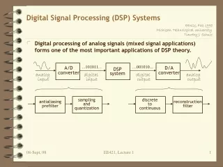
Some DSP Application Building Blocks (1) • The most commonly used DSP functions are • FIR (Finite Impulse response) filters, • IIR (Infinite Impulse response) filters, • FFT (Fast Fourier Transform), • DCT (Direct Cosine Transform), • Encoder/Decoder and Error Correction/Detection functions. • All of these blocks perform intensive arithmetic operations such as • add, subtract, multiply, multiply-add or multiply-accumulate.
Some DSP Application Building Blocks (2) A B Sum Q D Clr Clk MAC unit Bit-Serial Adder unit
Some DSP Application Building Blocks (3) Input[7:0] Input[7:4] Input[3:0] ROM 16x12 bits Addr[3:0] ROM 16x12 bits Addr[3:0] LPP[11:0] UPP[11:0] 12 bit Adder LPP[3:0] Sum Sum 8-bit by 8-bit Parallel Distributed Arithmetic Multiplier
Some DSP Application Building Blocks (4) • Efficient Memory Structures (LUTs) • Filters - IIR, FIR, LMS, etc. • Fast Fourier Transforms (FFT) • Discrete Cosine Transform (DCT) • Discrete Wavelet Transform (DWT)
Some FPGA Centric DSP Design Tools and Languages • Assembly, C, C++ • VHDL/Verilog (RTL code) • Xilinx EDK • Xilinx ISE • Mentor Graphic Modelsim • Xilinx Core Generator • MATLAB/Simulink • Xilinx System Generator
Topics Covered • Implementation Consideration for FPGA-Based Adaptive Transversal Filter Design. • Fast Discrete Wavelet Transformation Using FPGAs and Distributed Arithmetic • ENG6090 Project Status: Image Compression using Wavelet Filter Bank on Reconfigurable Computing System
Implementation Consideration for FPGA-Based Adaptive Transversal Filter Design Andrew Y. Lin, Master Thesis, University of Florida, 2003
Problem Statement and Purpose of the Design • Due to finite precisions in digital hardware, quantization must be performed in either or all of the following areas: • Input and reference signals; • Product quantization in convolution stage; • Coefficient quantization in adaptation stage. • Quantization noise is introduced in all of the above areas. The effects of quantization are discussed in this thesis. • This thesis also investigates the performance among FGPAs and DSP processors in terms of speed and power consumption.
Adaptive Algorithms, Finite Precision Effects on Adaptive Algorithms (1) -- Rounding Efforts • E is the expectation of the rounding error • X is the error caused by rounding • q is the quantizing steps • P is pdf function • σ is power spectral density of the rounding error
Adaptive Algorithms, Finite Precision Effects on Adaptive Algorithms (2) -- Truncatoin Efforts • E is the expectation of the truncation error • X is the error caused by truncation • q is the quantizing steps • P is pdf function • σ is power spectral density of the truncation error
Adaptive Algorithms, Finite Precision Effects on Adaptive Algorithms (3) -- Rounding Efforts on LMS filter • Input Quantization Effects (AD) ε(nT) is the quantization noise • Arithmetic Rounding Effects • Product Rounding Effects • Coefficient Rounding Effects • Rounding Effects at the Adaptation Stage • Effects Rounding at the Convolution Stage • LMS filter Slowdown and Stalling • Saturation • Using the clamping technique in which upon detecting saturation, the result is “clamped” to the most positive or most negative number, depending on the sign bit. • Alternatively, the sign algorithm is another way to reduce/avoid stalling.
Implementation of an Integer Based Adaptive Noise Canceller in Stratix Devices (1)--Software Simulation • The sampled desired discrete signal, composed of both the speaker’s speech and the vacuum noise, is served as the Noise Canceller’s reference signal; another vacuum noise, also sampled, is served as the filter’s primary input signal. Upon processing, the vacuumnoise will be reduced due to the adaptation of the filter tap weights. And the error signal produced by the adaptive system is in close resemblance of the original speech.
Implementation of an Integer Based Adaptive Noise Canceller in Stratix Devices (2)--Software Simulation Results • Since the primary and reference signal quantization is unavoidable due to A/D conversion, the only source of error that can be controlled by the designer is then product quantization noise at both theconvolution stage and the adaptation stage.
Implementation of an Integer Based Adaptive Noise Canceller in Stratix Devices (3)--Hardware Implementation • The newest FPGA families, Altera’s Stratix device family for example, incorporates embedded DSP blocks within the FPGA chip to have dedicated circuitry to perform common DSP operations including multiply and accumulate. • This family of FPGA devices is compared with another family of FPGA devices that does not include embedded DSP blocks. • DSP applications including adaptive systems have traditionally been implemented using general-purpose DSP processors due to their ability to perform fast arithmetic operations.
Implementation of an Integer Based Adaptive Noise Canceller in Stratix Devices (4)--Hardware Implementation • Hardware Block Diagram
Conclusion (1)--Stratix vs Traditional FPGAs • Speed and Area Comparison Stratix—with on-chip DSP components APEX—traditional FPGA without DSP components
Conclusion (2)-- FPGAs vs DSP Processors • Power Consumption Comparison Stratix – with on-chip DSP components TMS320VC33, DSP56390 – Traditional DSP devices
Fast Discrete Wavelet Transformation Using FPGAs and Distributed Arithmetic Ali M. Al-Haj, Department of Electronics Engineering, Princess Sumaya University for Technology, Al-Jubeiha P.O. Box 1438, Amman 11941, Jordan, 2003
Problem Statement and Purpose of the Design • programming such multiprocessor systems is a tedious, difficult, and time consuming task. • multiprocessor implementations of the discrete wavelet transform are not cost effective since parallelism comes at the expense of augmenting the system with more processing engines operating in parallel. • Custom VLSI circuits are inherently inflexible and their development is costly and time consuming, and thus they are not an attractive option for implementing the wavelet transform • FPGAs maintain the advantages of the custom functionality of VLSI ASIC devices, while avoiding the high development costs and the inability to make design modifications after production. Furthermore, FPGAs inherit design flexibility and adaptability of software implementations. • Our discrete wavelet transform implementation is exploiting the natural match between the Virtex architecture and distributed arithmetic
Basic Wavelet Computation • System diagram and wavelet coefficients
Distributed Arithmetic & Virtex FPGAs (1)-- Distributed Arithmetic • Let the variable Y hold the result of an inner product operation between a data vector x and a coefficient vector a. The conventional representation the inner product operation is given as follows: • Where the input data words xi have been represented by the 2’s complement number presentation in order to bound number growth under multiplication. The variable xij is the jth bit of the xi word which is Boolean, B is the number of bits of each input data word and x0i is the sign bit.
Distributed Arithmetic & Virtex FPGAs (1)-- Distributed Arithmetic • Distributed Arithmetic implemented in FPGA
Distributed arithmetic implementation • Distributed Arithmetic Filter implemented in FPGA
Functional simulation • Forward and Inverse DWT function simulation
Performance evaluation (1) • Speed comparison between conventional arithmetic implementation and distributed arithmetic implementation
Performance evaluation (2) • Resource usage comparison between conventional arithmetic implementation and distributed arithmetic implementation
Conclusion and Further Work (1)-- Conclusions • Two Implementations using the highly parallel Virtex filed programmable gate array devices (FPGAs), and two software implementations; one using the TMS320C6711 digital signal processor and the other using the 800 MHz Pentium III Intel processor. • Implementation which was based on the distributed arithmeticalgorithm achieved the best performance results. • Two software implementations were far inferior to the FPGA implementations in terms of execution speed. • The TMS320C6711 digital signal processor performed much better than the Pentium III , however, its performance is still much lower the performance of the least efficient, direct FPGA implementation • Using FPGAs, coupled with reformulating the computation of the wavelet transform in accordance with the distributed arithmetic algorithm, results in the performance levels required for real-time implementations.
Conclusion and Further Work (2)-- Further Work • After completing this FPGA implementation of the discrete wavelet transform and its inverse, we are now working on integrating a whole wavelet-based image compression system on a single, dynamic, runtime reconfigurable FPGA. • A typical image compression system consists of an encoder and a decoder. At the encoder side, an image is first transformed to the frequency domain using the forward discrete wavelet transform. • The non-negligible wavelet coefficients are then quantized, and finally encoded using an appropriate entropy encoder. The decoder side reverses the whole encoding procedure described above. • Transforming the 2-D image data can be done simply by inserting a matrix transpose module between two 1-D discrete wavelet transform modules such as those described in this paper.
Image Compression using Wavelet Filter Bank on Reconfigurable Computing System Oliver Liu ENGG*6090 : Project of Reconfigurable Computing Systems Winter 2007
Outline • Problem Statement and Purpose of the Design Experiment Environment • Transform and Coding Algorithms • Software Implementation • SW/HW implementation (on going) • Hardware Implementation (on going) • Results • Conclusion
Problem Statement and Purpose of the Design (1)--Introduction • A typical image compression system consists of an encoder and a decoder. At the encoder side, an image is first transformed to the frequency domain using the forward discrete wavelet transform. • The non-negligible wavelet coefficients are then quantized, and finally encoded using an appropriate entropy encoder. The decoder side reverses the whole encoding procedure described above. • An image compression system will be implemented using Reconfigurable Computing Platform.
Problem Statement and Purpose of the Design (2)-- System Diagram Forward Wavelet Filter Bank HP Sub-Image Huffman Coding LP Sub Image Run-length Coding Backward Wavelet Filter Bank HP Sub-Image Huffman decoding LP Sub Image Run-length decoding
Problem Statement and Purpose of the Design (3)-- Problem Definition • One implementation is to implement the transforming, quantization and codingall in software and run them on a microprocessor on a FPGA. • Other implementations will put either one or all of the transforming, quantization or coding to hardware and rest of them run on a microprocessor on the FPGA. • A RTOS will be used to observe the performance of different implementations controlled by multi-processes.
Xilinx Multimedia Board • The on-board Xilinx Vertex-II xc2v200 is used to implement different architecture. • The on-board external 2M memory will be used to store compressed and decompressed images and original image. • The MFS file system is being used to store image files. • Xilinx real time operation system kernel xikernel is being used in this design.
Transform and Coding Algorithms(1) -- Wavelet Filter Bank • System diagram and wavelet coefficients
Transform and Coding Algorithms(2) – Huffman Coding 1 1 0 Length Code Source Probability 0 1 2 11 a1 0.20 0 2 10 a2 0.19 1 3 011 a3 0.18 0 3 101 a4 0.17 1 3 001 a5 0.15 1 4 0001 a6 0.10 0 0 4 0000 a7 0.01
Transform and Coding Algorithms(3) – Run Length Coding (RLC) Consider a character run of 15 'A' characters which normally would require 15 bytes to store : With RLE, this would only require two bytes to store, the count (15) is stored as the first byte and the symbol (A) as the second byte.
Software Implementation Online Demo
Hardware Implementation On Going...
Thank You Questions ?