Download

1 / 21
210 likes | 374 Views
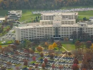
Milton S. Hershey Medical Center Biomedical Research Building. Joshua Zolko , Structural Option. Introduction. Table of Contents Introduction Architecture Structure Process HVAC Lighting Acoustics. The Biomedical Research Building (BMR) is located in Hershey, Pennsylvania.

E N D
Milton S. Hershey Medical Center Biomedical Research Building Joshua Zolko, Structural Option
Introduction • Table of Contents • Introduction • Architecture • Structure • Process • HVAC • Lighting • Acoustics • The Biomedical Research Building (BMR) is located in Hershey, Pennsylvania. • 245000 sq. ft, in 7 stories above grade • Built between 1991-1993 • Cost $49 million • Used a Bid-Build project delivery method • Used for Education and Laboratory space
Architecture • Table of Contents • Introduction • Architecture • Structure • Process • HVAC • Lighting • Acoustics • Façade of the BMR consists of long horizontal concrete and limestone slabs, and black glazing • Façade designed to relate to buildings already existing on campus • Cylinder and Planar wall on corners add to the otherwise flat building
Structure • Table of Contents • Introduction • Architecture • Structure • Process • HVAC • Lighting • Acoustics • The BMR is a monolithic concrete structure, using a one-way flat plate system with the average column size about 22” by 22” • Building sits on a deep foundation system of caissons 3 to 7 feet in diameter
Structure • Table of Contents • Introduction • Architecture • Structure • Process • HVAC • Lighting • Acoustics • Analysis shows that columns have an extra 35% capacity for applied loads • Design of the lateral system maintained symmetry, resulting in only a 6” eccentricity.
Process • Table of Contents • Introduction • Architecture • Structure • Process • HVAC • Lighting • Acoustics • Based on extra capacity of columns, goal was to be adding 3 extra stories to top of building, top story floor to floor height to be 24.6’ instead of the average 12.3’ • This extra space would serve for a studio or recreational setting for students.
Typical Column Section Process • Table of Contents • Introduction • Architecture • Structure • Process • HVAC • Lighting • Acoustics • Assumed gravity loads were to be: • 150 PSF dead • 40 PSF snow • 15 PSF superimposed • 80 PSF live • Self weight of the columns and bracing beams factored in as well
Process • Table of Contents • Introduction • Architecture • Structure • Process • HVAC • Lighting • Acoustics • Axial Loads calculated for a typical column over a 21’ by 35’ bay area. • As loads increase, they approach total capacity • This does not allow much room for applied moments from lateral or asymmetrical loading
Process • Table of Contents • Introduction • Architecture • Structure • Process • HVAC • Lighting • Acoustics • Loads were calculated again for the 1st, 2nd and 3rd floors, using live load reduction of 53% • Exceptions were used for live loads over 100 PSF, per IBC, at 20% • Allows more room for moments
Example Calculation Process • Table of Contents • Introduction • Architecture • Structure • Process • HVAC • Lighting • Acoustics • Loads were calculated again for the 1st, 2nd and 3rd floors, using live load reduction of 53% • Exceptions were used for live loads over 100 PSF, per IBC, at 20% • Allows more room for moments • Minimum allowance: 32% for 31%
Bracing Beam Section Process • Table of Contents • Introduction • Architecture • Structure • Process • HVAC • Lighting • Acoustics • Bracing beams were necessitated through exceptionally long columns, about 22’ in height • Beams were chosen to be 24” by 24” to match column sizes • Would allow for an architectural feature on the top floor.
Bracing Beam Section Process • Table of Contents • Introduction • Architecture • Structure • Process • HVAC • Lighting • Acoustics • Assumed a 15 PSF superimposed load for mechanical and electrical equipment • 600 PLF dead load. • 66 and 96 ft*kip moments necessitate 4 #7 rebar • Torsion and shear reinforcement was found to be negligible according to ACI
RAM Model Process • Table of Contents • Introduction • Architecture • Structure • Process • HVAC • Lighting • Acoustics • A RAM Model was developed to analyze the effect of controlling wind and earthquake forces. • Addition was designed maintaining symmetry and negligible eccentricity as rest of building, minimizing unusual torsional effect and forces
Story Drifts Process • Table of Contents • Introduction • Architecture • Structure • Process • HVAC • Lighting • Acoustics • Distributing story shear forces across all columns on a story by a factor of 1.5%, lead to a shear force of 9 kips • Moment of 111 ft*kips per column • Story and Total drifts are well within acceptable H/400 limits • Overturning is controlled by gravity loads
Story Drifts Process • Table of Contents • Introduction • Architecture • Structure • Process • HVAC • Lighting • Acoustics • Distributing story shear forces across all columns on a story by a factor of 1.5%, lead to a shear force of 9 kips • Moment of 111 ft*kips per column • Story and Total drifts are well within acceptable H/400 limits • Overturning is controlled by gravity loads
Story Drifts Process • Table of Contents • Introduction • Architecture • Structure • Process • HVAC • Lighting • Acoustics • Distributing story shear forces across all columns on a story by a factor of 1.5%, lead to a shear force of 9 kips • Moment of 111 ft*kips per column • Story and Total drifts are well within acceptable H/400 limits • Overturning is controlled by gravity loads
Story Drifts Process • Table of Contents • Introduction • Architecture • Structure • Process • HVAC • Lighting • Acoustics • Distributing story shear forces across all columns on a story by a factor of 1.5%, lead to a shear force of 9 kips • Moment of 111 ft*kips per column • Story and Total drifts are well within acceptable H/400 limits • Overturning is controlled by gravity loads
Insulation HVAC (Breadth 1) • Table of Contents • Introduction • Architecture • Structure • Process • HVAC • Lighting • Acoustics • Calculated CFM requirements for the addition were found to be 86000 CFM • 4050 people at 20 CFM and 81000 sqft at .06 CFM • BTU Loads for CFM and people and insulation were found to be 5 million BTU/HR for both heating and cooling
Typical Luminaire Lighting (Breadth 2) • Table of Contents • Introduction • Architecture • Structure • Process • HVAC • Lighting • Acoustics • For a recommended 500 lux for a work space, the total room of 90’ by 210’ with its 12 bays requires 200 luminaries, allowing 18 per bay • Two systems were developed, one at 12.3’ high, and one at ceiling for the top story, but ceiling height would cast shadows
Calculations Acoustics (Breadth 3) • Table of Contents • Introduction • Architecture • Structure • Process • HVAC • Lighting • Acoustics • Acoustical tile was initially placed on ceiling, beams, columns, and carpeting was used. • Created a “dead space” which would have been disconcerting to occupants • Toned back acoustical insulation to just beams and columns, as well as carpeting


![[PDF READ ONLINE] Who Was Milton Hershey?](https://cdn7.slideserve.com/12521285/slide1-dt.jpg)