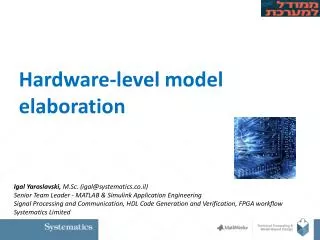
HDL Code Generation using MATLAB/Simulink
HDL Code Generation using MATLAB/Simulink. Milica Ristović, Slobodan Lubura University of East Sarajevo, Faculty of Electrical Engineering . Verilog i HDL codes can be generated from one of these models: - Simulink model;

HDL Code Generation using MATLAB/Simulink
E N D
Presentation Transcript
HDL Code Generation using MATLAB/Simulink Milica Ristović, Slobodan Lubura University of East Sarajevo, Faculty of Electrical Engineering
Verilogi HDL codes can be generated from one of these models: - Simulink model; -Stateflow diagram; -Embedded MATLAB model.
Steps which are neccessary for HDL Code generation in Simulink: • Design HDL compatible Simulink model; • Data type conversion from floating-point to fixed-point; • Use tool for compatibility check (it leads to eventual errors or problems, made durring generation); • HDL Code Generation; • Analyze of Generated HDL Code; • Implementation of Code on FPGA board or another similar device, analyze of device.
Fixed-point • Application “Simulink Fixed-point” expands possibilities of Simulink environment and enables using Data types in fixed-point format. • Data Type Conversion • fixdt(x,y,z), where x is number of bits, y number of bits of real part, and z number of bits of fractional part.
Compatibility check with HDL Coder Using „HDL Code Generation“ panel:Choosing „Run Compatibility Checker“; 2) Right click on subsystem which HDL Code is going to be generated, choosing HDL Code Generation Check Subsystem Compatibility; 3) Writing command in command window: >> checkhdl(‘Name_of_model', ‘Name_of_subsystem'); If model is not COMPLETELY compatible with HDL Coder, code generation will not be done!
HDL Code Generation Using „HDL Code Generation“ panel:Choosing „Generate“; 2) Right click on subsystem which HDL Code is going to be generated, choosing HDL Code Generation Generate HDL for Subsystem; 3) Writing command in command window: >> makehdl (‘Name_of_model', ‘Name_of_subsystem'); Message: # # # HDL Code Generation Complete means end of proccess of HDL Code Generation.
Report of generated HDL code • Report has some parts from which we can get these information: • information about version of HDL Code, and creating date; • insight in virtual blocks, which cannot be seen in the model, unlike of real blocks (Simulink blocks), giving us mapping between elements (blocks and subsystems) of model and code: • Code–model links, clicking them we can see part of subsystem or block that is cide generated for; • Model–code links, enable to see generated code for any block in the model. • ( HDL Code Generation Navigate to Code )
Implementation of CORDIC Algorithm on • FPGA Altera Cyclone II • Coordinate Rotation DIgital Computer - taken from Simulink demos models – adaptation is neccessary
Implementation of CORDIC Algorithm on FPGA Altera Cyclone II Adapted CORDIC model:
Implementation of CORDIC Algorithm on • FPGA Altera Cyclone II • CORDIC Algorithm model in Quartus:
Implementation of CORDIC Algorithm on • FPGA Altera Cyclone II • Waveforms used for testing CORDIC Algorithm in Quartus: