Download

1 / 24
240 likes | 377 Views
Design of a Monitoring and Control System for Residential Power Management. Design Team Adam Brunella Brian Kostura Justin Gilmore Scott Tibai. Project Overview. Energy Savings Standby power on electrical devices can be as high as 10-15 watts though about .3 watts is typical

E N D
Design of a Monitoring and Control System for Residential Power Management Design Team Adam Brunella Brian Kostura Justin Gilmore Scott Tibai
Energy Savings Standby power on electrical devices can be as high as 10-15 watts though about .3 watts is typical Quality of life Gives the user more information and control over their homes. Cost Similar systems are expensive Benefits to Society
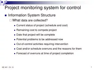
System Requirements • A web based interface that will allow users to control their system from anywhere with an Internet connection. • IEEE 802.15.4 standard • Distinguish among and communicate with multiple switches on the same network. • A server that will handle the user requests and generate the control signal for the switch. • The server will require user authentication in the form of a log-in, and a database that stores information and previous history.
System Requirments • A 120VAC switch that can be controlled via a home wireless network. • Handle loads up to 15A at 120V. • The switch module needs to be able to fit inside a standard wall receptacle box and be able to be inserted through a hole smaller than a standard switch cover.
User Interface • Built using Vaadin - Java Framework for Web Applications • MySQL Database Interaction • Execution of Queries and Modification of Tables • Xbee Module Communication • Only Authorized User Access
Transformer Steps down the voltage from 120Vac to 5VAC (8.6VAC actual) Full bridge rectifier Converts the supply voltage from AC to DC Linear voltage regulator Capacitors in conjunction with regulator to smooth 5VDC to the Xbee module Power Circuit
Xbee microcontroller Receives control signals from the base module via RF Actuates relays on/off with 1.2VDC Solid state relays Connection is closed only when they receive voltage from the microcontroller Two SPST relays represent a physical three way switch Turn the controlled circuit on and off Control Circuit
Monitoring Circuit • Transformer • Steps down the voltage from 120Vac to 5Vac • Full bridge rectifier • Converts the supply voltage from AC to DC • Linear voltage regulator • Smooths out signal to get a constant 3.3VDC as an input to the Xbee module
XBee 1mW Chip Antenna • Meet IEEE 802.15.4 standard • Operate on 2.4 GHz Frequency Band • 8 I/O Pins • Use the xbee-api by Andrew Rapp, to communicate with the modules with Sun Java programming language
Three Different Types of ZigBees: • ZigBee coordinator (ZC): The most capable device, the coordinator forms the root of the network tree and might bridge to other networks. There is exactly one ZigBee coordinator in each network since it is the device that started the network originally. • ZigBee Router (ZR): As well as running an application function, a router can act as an intermediate router, passing on data from other devices. • ZigBee End Device (ZED): Contains just enough functionality to talk to the parent node; it cannot relay data from other devices. This relationship allows the node to be asleep a significant amount of the time.
Future Updates • Reduce size of physical components • Integrate latching relays • Enclose system • Updates to user interface
System to control a residential circuit Wirelessly over the internet or manually Only visible part is the light switch Server that contains user information and control software Conclusion
References "Standby Power." Wikipedia, the Free Encyclopedia. Web. 10 Apr. 2011. <http://en.wikipedia.org/wiki/Standby_power>. Rapp, Andrew. "Xbee-api - A Java API for Digi XBee/XBee-Pro OEM RF Modules - Google Project Hosting." Google Code. 2011. Web. 26 Apr. 2011. <http://code.google.com/p/xbee-api/>.