Sensors
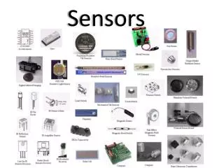
Sensors. BADI Year 3 John Errington MSc. Sensors. Allow a design to respond to its environment – e.g. a line following robot may use photosensors to detect a paint line on the floor.

Sensors
E N D
Presentation Transcript
Sensors BADI Year 3 John Errington MSc
Sensors • Allow a design to respond to its environment – e.g. a line following robot may use photosensors to detect a paint line on the floor. • Enable systems to determine when the required action has been completed; for example a trip switch will indicate that a lift has reached the desired floor.
Trip switches Perhaps the most common sensor used in industry is the trip switch or limit switch – a simple microswitch in an industry-sealed case with a rugged mechanical activation system such as a lever + roller as shown above
Strain gauges Also extremely widely used, strain gauges measure the amount of extension or compression experienced by the material it is fastened to. This gives a measure of the strain, and can thus be used to measure deformation or applied load.
Optical sensors • Photodiodes and phototransistors • Integrated photoswitches • Light dependent resistors • Diode arrays (1d & 2d) • CCTV & digital cameras • Low light sensors e.g. photomultipliers • No moving parts so inherently reliable BUT • Susceptible to dirt and changes in ambient light
OptoSwitches Sensors comprising a light source, photodiode and amplifier Diffuse scan – detects reflected light Through scan – detects when beam is interrupted Hall effect sensor also shown here detects when a ferrous metal breaks the magnetic field
Types: Mechanical Inductive Capacitive Ultrasonic Optical Application etc. Contact sensing Ferrous only 1cm Metals only 1cm 6m range solid/liquid/powder Through beam or Reflective Clean environments only Proximity sensors
Non-contact sensors (1) Inductive proximity sensor Capacitive proximity sensor C2 C1 P S C3 Coil inductance increases as iron / steel object (S ) gets closer, because lines of magnetic flux can flow through the iron, making the effective path shorter. Capacitance increases as metal object (P) gets closer because additional capacitance paths C2 & C3 are added and increase in value as the separation reduces. C1 is always present.
Non-contact sensors (2) Other non-contact sensors use sound (ultrasonic) or electromagnetic waves (light, microwaves, etc.) to gather information about the distance between the sensor and a surface. Microwave sensors are reliable in dirty industrial environments but exposure of personnel must be prevented.
Proximity switches Capacitive, Ultrasonic Inductive
Rotary and linear position • Potentiometric (sliding contact) • LVDT • Encoders Main issues: operating conditions, reliability, analog or digital output Contact or non contact - is wear important?
Magnetic pick-ups Often used to detect engine timing by counting teeth on the starter gear. Robust, reliable non-contact
Rotary shaft encoder Gives a digital output indicating the angular position of a shaft. They often use a disk with marks like a bar code, that are read by optical photodetectors inside the encoder. Robust, reliable non-contact.
Absolute rotary encoder An absolute encoder has a number of binary outputs that indicate the switch shaft's absolute rotational position referenced to some spot on the switch's body. For example, a three bit absolute rotary encoder will divide the rotational position into eight sectors. Absolute encoders are available in a variety of style with a variety of resolutions.
Incremental rotary encoder An incremental rotary encoder won't tell you where the shaft is positioned. It will only tell which direction the shaft is being turned and how fast. Incremental encoders have two outputs called phases. Each outputs a square wave. Turning the shaft one direction causes one phase to lead the other by 90 degrees. Reversing the direction will cause the other phase to lead. The frequency of the output is proportional to the rotational speed of the shaft.
Linear position • Linear Variable Differential Transformer • Other (cheaper!) linear position sensors use a resistive track and slider but this is less precise and reliable due to wear of the track
+ - Potentiometric sensors Resistive track may be wire wound on a former, metal film or graphite on substrate L x Vs Vout The voltage picked off is proportional to the position of the sliding contact Vout = Vs * x / L
Open loop control • Simple and easy to implement • No feedback of controlled parameter • No certainty that parameter is at desired value • Change in system parameters such as load will result in a deviation from the desired value
Servo systems Measure output variable Compare to desired value Amplify the difference Apply to correct the error Result: servo system can adjust for changes in load, amplifier gain etc and still give good compliance with required value