Download
1 / 18
180 likes | 297 Views
This guide explains how to determine the location of images formed by convex and concave lenses through ray tracing. It details the paths of three rays originating from the top of an object placed before a convex lens and outlines the rules for finding the resulting image's position mathematically. Key concepts like real and virtual images, focal length, and lens characteristics are discussed. Additionally, it covers how multiple lenses interact and the optical aberrations affecting image quality.

E N D
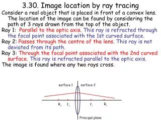
3.30. Image location by ray tracing Consider a real object that is placed in front of a convex lens. The location of the image can be found by considering the path of 3 rays drawn from the top of the object. Ray 1: Parallel to the optic axis. This ray is refracted through the focal point associated with the 1st curved surface. Ray 2: Passes through the centre of the lens. This ray is not deviated from its path. Ray 3: Through the focal point associated with the 2nd curved surface.This ray is refracted parallel to the optic axis. The image is found where any two rays cross.
3.30 Ray Tracing for a convex lens O I R1 R2 F2 F1 Ray 1, Ray 2, Ray 3
3.31 Mathematical method for finding image position O I R1 R2 F2 F1 Ray 1, Ray 2, Ray 3
3.31 Mathematical method for finding image position Let the object O, of height H1, be placed a distance p from the lens of focal length f. The resulting image I, of height H2, is formed a distance q from the lens. The lens is symmetric (R1 = R2). p H1 O H2 b a a b I R The ray through the centre of the lens makes an angle a with optic axis. F q The ray through the focal point of the lens makes an angle b with optic axis.
Considering the ray through the center of the lens gives tana = H1/p and tana = H2/q Considering the ray through the center of the lens gives tanb = H2/(q-f) And tanb = H1/f So H2/q = H1/p and H2/(q-f) = H1/f
As H2/q = H1/p and H2/(q-f) = H1/f Then H2/ H1 = q/p and H2/ H1 = (q-f) /f So q/p =(q-f) /f Multiply both sides by fp qf = pq - pf Divide both sides by pfq 1/p = 1/f - 1/q Re-arrange to give This is the equation that links the focal length, object and image distances. NOTE
3.32 Examples of image location with a convex lens We know that the focal length f, object distance p and image distance q are related by • Where is the image formed if: • A real object is located at infinity? • Here 1/p = 0. Thus q = f • The image is real and inverted • A real object is located at the radius of curvature, R. • Here p = R and R = 2f. • Thus p = 2f and so q = 2f. • Object and image located the same distance from the lens but on opposite sides of the lens. • The image is real and inverted.
A real object is located at f. • Here p = f and so 1/q = 0. • Image formed at infinity • The image is real and inverted • A real object is located at f/2 • Here 1/p = 2/f. Thus q = -f • So image formed is virtual and appears to be on the same side of the lens as the object. • The image is erect • When a real object is placed between the focal point and the convex lens the image is virtual.
O I R1 R2 F2 F1 3.33 Why is an image real when p > f? When p > f the light that is reflected by the lens converges to a point on the opposite side of the lens to the object. Hence the energy in the rays passes through the point where the image is formed.
3.34 Why is an image virtual when p < f? I O F F When p < f the light refracted by the convex lens diverges. To find the point where the rays appear to cross they must be projected back to the side of the lens where the object is. Hence the image is virtual.
3.35. Image formation by a concave lens • For a concave lens the focal length is negative, assuming that the lens is surrounded by a material of lower refractive index. This means that the focal point of the first refracting surface is located on the same side as the object. • As a result a real object placed anywhere in front of the lens will produce a virtual image. • Why does this happen?
3.35. Image formation by a concave lens • Here the lens makes the rays diverge. The image is found by tracing the rays back to the point where they appear to cross. O I F The purple ray is offset for clarity
3.36. Image formation by two lenses • Assume that we have two thin lenses of focal length f1 and f2 respectively placed side by side. • Let the object be placed a distance p from the principal plane of the first lens. • The first lens surface generates an image which is located a distance s from the principal plane. • This image then acts as an object for the second lens. • The resulting image is formed a distance q from the principal plane associated with the second lens. f1 f2 p q
For the first lens we find that the image and object distances are related by • For the second lens we find that the image and object distances are related by The minus sign in front of1/s is a consequence of using the image generated by the first lens as the object for the second lens. The effective focal length ft is given by
3.37. Defects caused by reflections • There are several defects that affect thin lenses which are • Astigmatism: Here the radius of curvature varies over the lens surface. Hence different rays are brought to a focus at different points. This causes a blurring of the image. • Spherical aberration: When deriving the thin lens formula we assumed that all the rays propagated through the lens close to the optic axis and made small angles with respect to the optic axis. For a real lens this is not necessarily the case and in general the rays that hit the lens at the edge are focused at a different point when compared with those that strike the lens close to the centre. This problem leads to a blurring of the image but can be overcome by sharing the refraction over many optical elements. • Chromatic aberration: Here different colours are brought to a different focal point. Blue rays are focused closer to the lens when compared to red rays. Thus there appears to be a depth to the focus which varies in colour. This effect is caused by the wavelength dependent nature of the refractive index. This problem can be over come by use of an achromatic doublet.
3.37. Chromatic Aberration Blue, green and red rays focused at different points Achromatic doublet Blue, green and red rays focused at same point
Achromatic doublet Blue, green and red rays focused at same point 3.37. Chromatic Aberration The two lenses are made from different materials with different refractive indices. This means that the dispersive power w of each lens is different. The focal lengths of each lens are then chosen such that the following condition is satisfied w1/f1 = w2/f2 . This means that the chromatic aberration induced by the first lens is counteracted by the second lens.