Download

1 / 12
850 likes | 2.55k Views
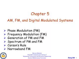
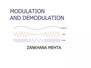
FM MODULATION AND DEMODULATION. Angle Modulation. To generate angle modulation, the amplitude of the modulated carrier is held constant and either the phase or the time derivative of the phase is varied linearly with the message signal. General Forms.

E N D
Angle Modulation • To generate angle modulation, the amplitude of the modulated carrier is held constant and either the phase or the time derivative of the phase is varied linearly with the message signal.
General Forms • The expression for an angle modulated signal is: • The instantaneous phase of s(t) is: • The instantaneous frequency of s(t) is:
Phase Modulation • For phase modulation: Where; kp : sensitivity in rad/v • Hence, the general form of the PM signal is:
Frequency Modulation • For frequency modulation: By then Where; kf : sensitivity in Hz/v • Hence, the general form of the FM signal is:
Instantaneous Frequency • The instantaneous frequency for FM signals is: • Note: The instantaneous frequency; fi(t) will have the same shape of that of the message since the message is hidden in the frequency.
FM Modulation Index & Bandwidth • The FM modulation index β is defined as the peak frequency derivation dividedby the message frequency. • It is given by the following formula: • Carson’s rule: A 98% power bandwidth can be obtained using the simple formula:
Generation of FM signals • In a direct FM, the instantaneous frequency of the carrier is varied in accordance with m(t) by means of a voltage – controlled oscillator (VCO). • VCO is a linear frequency modulator. It is an oscillator with a voltage reactance that controls the oscillator output frequency • The instantaneous frequency of the VCO is given by: • The VCO Characteristics :
- The VCO output is: - The VCO output represents the FM signal.
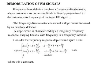
FM Demodulation • Phase Locked Loop: - PLL is a negative feedback control loop in which the feedback signal is used to lock the output frequency and phase of any input signal. - The block diagram of PLL:
PLL Components 1. Phase detector ( phase comparator): It is a mixer (multiplier) followed by a low pass filter. The output voltage of the PD is a function of the phase difference between the two input signals. - If xi(t) represents the FM signal and xo(t) represents the VCO output : Hence:
- The low pass filter suppresses the high frequency term. Hence, the PD output is given by: - When the difference between the two phases is very small: Where; Kǿ is the PD sensitivity .