Download
1 / 21
210 likes | 398 Views
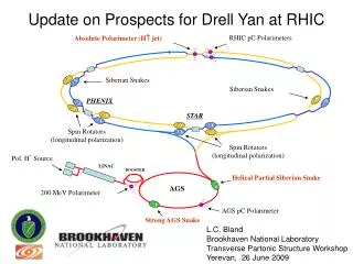
★. I nternal target option for RHIC Drell-Yan experiment Wolfram Fischer and Dejan Trbojevic. 31 October 2010 Santa Fe Polarized Drell-Yan Physics Workshop. Content. Layout of internal target experiment b * considerations, orbit correction

E N D
★ Internal target optionfor RHIC Drell-Yan experimentWolfram Fischer and Dejan Trbojevic 31 October 2010 Santa Fe Polarized Drell-Yan Physics Workshop
Content • Layout of internal target experimentb* considerations, orbit correction • Low density target option– 1015 atoms/cm2low density = operation in parallel to STAR and PHENIX • High density target option – 1017atoms/cm2highdensity = dedicate operation after store for STAR and PHENIX 2
Orbit effects • 2 dipoles (11, 3 mrad bend) with same polarity(RHIC arc dipoles bends 38 mrad) • Beams largely shielded (see next slide) • For comparison:RHIC orbit corrector has 0.3 mrad(at locations with larger b-functions) 4
Orbit effects If we drill a R=5 cm through hole, then field drops to 0.336 T (magnetic length will increased by 10 cm) By = 0.1662 T R = 5cm: 1.3 TmR = 2cm: 0.6 Tm + ~20% from 2nd magnet [RHIC arc dipole corrector: ~0.3 Tm ) Needs further work, likely not a showstopper for small radius. 5
b* considerations • Have operated BRAHMS mostly with b* = 3.0 m(until Run-6) • Have also used • b* = 2.0 m (d-Au at 100 GeV/nucleon, Run-3, lifetime/background problems) • b* = 2.5 m (Cu29+ at 100 GeV/nucleon, Run-5, lifetime/background problems) • b* = 3.0 m (Cu29+ at 11.2 GeV/nucleon, Run-5) • b* = 3.0 m (31.2 GeV p, Run-6) • b* = 2.0 m possible (perhaps even b* = 1.0 m) • [not critical for internal target, see next slide] • May need power supplies for local correctorscan be studied with dynamic aperture simulations (Y. Luo) 6
b* considerations • So far all consideration were for b* at nominal IP • Internal target is at s = -7.0 m where b should be as small as possible(to both maximize luminosity and minimize emittance growth of proton beam) • With b* at nominal IP: • bmin = 14m at s = -7m(reached for b* = 7 m) • RMS beam size for- bmin = 14m- en = 20 mm.mrad- 250 GeV protonsis 1 mm => need ~4 mm target width for full overlap 7
Beam lifetime with internal target D. Trbojevic tlifetime Nparticle number ttime ntarget density linteraction length (= circumference) frevolution frequency sNcross section for nuclear interactions leading to loss sCcross section for Coulomb interactions leading to loss [D. Trbojevic, “Beam lifetime and emittance growth in RHIC under normal operating conditions, with the hydrogen gas jet, the cluster jet and pellet targets”, BNL C-AD/AP/403 (2010)] 8
Emittance growth with internal target D. Trbojevic eNnormalize emittance bTWISStwiss function Q scattering angle mptarget density c speed of lightg Lorentz factor ZP, APparticle Z and A c speed of light LRADradiation length afine structure constant Nmgas density (molecules/g) ZT, ATtarget Z and A nmgas density (g/cm3) reclassical electron radius RTThomas-Fermi screening radius RNeffective radius of target nucleus [D. Trbojevic, “Beam lifetime and emittance growth in RHIC under normal operating conditions, with the hydrogen gas jet, the cluster jet and pellet targets”, BNL C-AD/AP/403 (2010)] 9
Low density internal target – 1015 atoms/cm2 • Low density H target (storage cell, cluster)for continuous operation in parallel to PHENIX and STAR • With 1015 atoms/cm2 • beam lifetime: tN = 15 hinitial loss rate of4x108 p/s+ secondary particles • luminosity lifetime:tN< 7.5 h • emittance growth: deN/dt ~ 10-2 mm mrad/h • luminosity loss to PHENIX and STAR (10 h store): ~% range • Need to reduce target density by about factor 3-5 tN ~ 50 h without target under current conditions 10
Beam lifetime in Run-8 pp (100 GeV) Intensity fitted to N(t) = A*exp(-t/t1) + (1-A)*exp(-t/t2) [first 3h] slow part, A = 10% 50 h slow part, 1-A = 90% Expect proton beam lifetimes at 250 GeV to approach these values in the future. 11
Luminosity lifetime in Run-8 pp (100 GeV) Luminosity fitted to L(t) = A*exp(-t/t1) + (1-A)*exp(-t/t2) [first 3h] slow part, A = 12% 14 h slow part, 1-A = 88% Expect proton beam lifetimes at 250 GeV to approach these values in the future. 12
High density internal target – 1017 atoms/cm2 • High density target (pellet, solid)for end-of-store operation after PHENIX and STAR • With 1017 atoms/cm2 • beam lifetime: tN = 0.15 hinitial loss rate of4x1010 p/s+ secondary particles • emittance growth: deN/dt ~ 1 mm mrad/hcan cause beam losses in other parts of ring • luminosity loss to PHENIX and STAR (10 h store): ~2-3%due to lost time in overall cycleDY experiment becomes the beam dump 13
Luminosity loss to STAR and PHENIX for end-of-store operation operation ok right of line • Assumptions: • 12 h from beginning of store to next (without DY experiment) • end-of-store run with length of 1.5x beam lifetime (Nb,final = 0.22 xNb,initial) 14
High density internal target – 1017 atoms/cm2 • With high density target beam loss at internal target is similar to beam dump • Internal target will become effectively the beam dump • Will need shielding and radiation control like at dump • In particular need shielding for superconducting magnetsin area (especially DX) • Electronics in experimentalhall needs to be radiation hard 15
Polarized proton intensity upgrades • Bunch intensity • Polarized source upgrade under way10x intensity, ~5% more polarization (2013)could translate in about 3x10¹¹ p/bunch • new SAD/ASE(under way) • Number of bunches (>111) requires • new SAD/ASE (under way) • new RHIC injection system • likely in-situ coating of beam pipe (R&D under way) • possibly another dump upgrade (just finished one – beam pipe inserts) • improved machine protection system(loss control on ramp, during store) existing OPPIS In-situ pipe coating SEYand r reduction (start >2013) 16
Other ideas – target surrounding beam (E. Stephenson) Plan experiment to measure polarization at large amplitudes (M. Bai). 17
Summary • Internal target is an option for beam operation • Layout of internal target experimentorbit distortion with shielded fields probably okbmin = 7.5 m at s = -7 m, need ~4 mm target width for full overlap • Low density target option – 0.3x10¹⁵ atoms/cm2parasitic operation to STAR and PHENIX, (%-range luminosity loss) • High density target option – 3x10¹⁶ to 1017atoms/cm2end-of-store operation, few % luminosity loss to STAR and PHENIXtarget becomes beam dump • Higher bunch intensity upgrade under way 18
b* considerations • Field quality of triples in IR2 not as good as IR6 and IR8 • Local IR correctors installed in IR2 (like IR6 and IR8)but have currently no power supplies connectedhave used full complement in IR6/IR8 in operation: 6-poles, skew 6-poles, 8-poles, 10-poles, 12-poles • Small b* implies large bmax in triplets (b*bmax= const ~ 1.5 km)and therefore larger exposure of beam to triplet field errors • These cause emittance growth and beam lifetime reduction through the enhancement of chaotic particle motion (the reason for all beam loss) 20
b* considerations RHIC interaction region with nonlinear correctors [F. Pilat et al., “Non-linear effects in the RHIC interaction regions, …”, PAC 2003.] Full corrector set (like IR6/IR8): 14 ps per beamReduced set (6-pole, skew 6-pole): 4 ps per beamAbout $12k per 50A ps (+infrastructure, controls, and installation: ~$100k) 21