Download
1 / 92
930 likes | 1.14k Views
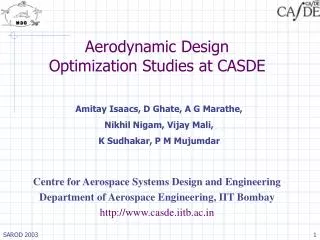
WingOpt - An MDO Research Tool for Concurrent Aerodynamic Shape and Structural Sizing Optimization of Flexible Aircraft Wings. Prof. P. M. Mujumdar, Prof. K. Sudhakar H. C. Ajmera, S. N. Abhyankar, M. Bhatia Dept. of Aerospace Engineering, IIT Bombay.

E N D
WingOpt - An MDO Research Tool for Concurrent Aerodynamic Shape and Structural Sizing Optimization of Flexible Aircraft Wings. Prof. P. M. Mujumdar, Prof. K. Sudhakar H. C. Ajmera, S. N. Abhyankar, M. Bhatia Dept. of Aerospace Engineering, IIT Bombay
Develop a software for MDO of aircraft wing - Study issues of integrating MDA for formal design optimization Aeroelastic optimization as an MDO problem - Concurrent aerodynamic shape and structural sizing optimization of a/c wing Realistic MDO problem - Showcase a reasonably complex aircraft design optimization problem with high fidelity analysis Aims and Objectives
Study different MDO architectures – reformulations of the optimization problem Influence of fidelity level of structural analysis Study computational performance Benchmark problem for MDO framework development Aims and Objectives
Design Drivers/Constraints for the WingOpt Architechture • Definition of a meaningful overall design problem based on available analysis and optimization capability • Limited disciplines considered: Geometry, Aerodynamics, Structures, Trim/Maneuver • Aeroelasticity as basis for coupling disciplines • Software integration within confines of high level programming languages (FORTRAN/C) through students • At least one discipline taken to its highest fidelity (structures) • Emulate some elements of a general purpose framework
Identify array of all variables/functions associated with the system analysis Identify all possible candidates for design variables/constraints Partition variables database to fixed and design parameters. Tag user codes to all variables/functions Define subset optimization problem through tags Create location look-up tables for selected subset variables/constraints Variables & Function Database
Types of Optimization Problems Structural sizing optimization Aerodynamic shape optimization Simultaneous aerodynamic and structural optimization Features of WingOpt
Flexibility Easy and quick setup of the design problem Aeroelastic module can be switched ON/OFF Selection of structural analysis (FEM / EPM) Selection of Optimizer (FFSQP / NPSOL) Selection of MDO Architecture (MDF / IDF) and their variants Design variable linking Load Case specification. Variables/design constraints attached to load cases Features of WingOpt
Software modules integrated • Gradient based optimizers • FFSQP; NPSOL (Source codes) • Aerodynamic Analyses • VLM (source code) • Semiempirical (Raymer/Roskam) (source code) • Structural Analyses • Equivalent Plate Method (source code) • Finite Element Method (commercial licensed software (executable)) • Source code integration with minimal modifications to code through I/O files
Architecture of WingOpt I/P processor Problem Setup Optimizer History I/P MDO Control Analysis Block O/P O/P processor INTERFACE
Baseline aircraft Boeing 737-200 Objective min. load carrying wing-box structural weight No. of span-wise stations 6 No. of intermediate spars (FEM) 2 Aerodynamic meshing 12*30 panels Optimizer FFSQP Test Problem
Design Variables Skin thicknesses - S Wing Loading Aspect ratio Sweep back angle t/croot Test Problem A
Constraints Stress – LC 1 fuel volume MDD – LC 3 Range – LC 2 Take-off distance Sectional Cl – LC 1 Test Problem - Structural - Geometric Aerodynamic
Aeroelasticity analysis leads to significant weight reduction Simultaneous structural and aerodynamic optimization significant impact on design IDF-AAO failed MDF1 loop stability not related to physical divergence Stability information in IDF and IDF-AAO cannot be captured Conclusions
In MDF1 time taken in aerodynamic very high compared to structures MDF1 most efficient, iteration convergence is fastest, however not fully reliable MDF2 and MDF-AAO are very robust and took almost same computational time Direct method much efficient than indirect method Conclusions
Simultaneous optimization are very time consuming With non-linearity (more time consuming analysis) IDF and AAO might be more benificial Maintaining history saves significant computational time Conclusions
Software for MDO of wing was developed Simultaneous structural and aerodynamic optimization Focused around aeroelasticity Handles internal loop instability MDO Architectures formulated and implemented Methods for accelerating convergence formulated and implement Multiple load case implemented User interface improved Summary
IDF and IDF-AAO for FEM Additional features Buckling composites Aileron control efficiency Multilevel MDO Architectures Non linear problem Parallel computation High fidelity aerodynamics analysis Future Work
Aerodynamic Geometry Structural Geometry Design Variables Load Case Functions Computed Optimization Problem Setup Examples Problem Formulation
Aerodynamic Geometry • Planform • Geometric Pre-twist • Camber • Wing t/c • single sweep, tapered wing • divided into stations • S, AR, λ, Λ y Λ AR = b2/S λ = citp/croot croot citp Wing stations b/2 x
Aerodynamic Geometry • Planform • Geometric Pre-twist • Camber • Wing t/c • constant α' per station • α'i, i = 1, N y x
Aerodynamic Geometry • Planform • Geometric Pre-twist • Camber • Wing t/c • formed by two quadratic curves • h/c, d/c Point of max. camber Second curve First curve h d c
Aerodynamic Geometry • Planform • Geometric Pre-twist • Camber • Wing t/c • linear variation in wing box-height stations t
A A Structural Geometry Cross-section Box height Skin thickness Spar/ribs • symmetric • front, mid & rear boxes • r1, r2 y Structural load carrying wing-box Front box r1 = l1/c r2 = l2/c A A Mid box Rear box l1 l2 c x
y A A x Structural Geometry Cross-section Box height Skin thickness Spar/ribs • linear variation in spanwise & chordwise direction • hroot , h'1i , h'2i ; where i = 1, N A A hfront hrear h'1 = hrear /hfront
y A A x Structural Geometry Cross-section Box height Skin thickness Spar/ribs • Constant skin thickness per span • tsi , where s = upper/lower • i = 1, N tupper A A tlower
y Structural Geometry Cross-section Box height Skin thickness Spar/ribs • modeled as caps • linear area variation along length • Asjki , where s = upper/lower • j = cap no.; k = 1,2; i =1, N A rib Aupper12 A A spar cap x 1 2 intermediate spar rear spar front spar
Wing loading Sweep Aspect ratio Taper ratio t/croot Mach number Jig twist* Camber* Skin thickness* Rib/spar position* Rib/spar cap area* t/c variation* wing-box chord-wise size and position Design Variables Aerodynamics Structures * Station-wise variables
Altitude (h) Mach number (M) ‘g’ pull (n) Aircraft weight (W) Engine thrust (T) Load Case Definition
Aerodynamics Sectional Cl (VLM) Overall CL (VLM) CD (VLM + empirical)) Take-off distance Range (Brueget) Drag divergence Mach number (Semi-empirical) Structural Stresses (σ1 , σ2) Load carrying Structural Weight(Wt) Deformation Function (w(x,y)) Geometric Fuel Volume (Vf) Functions Computed
Select objective function Select design variables and set its bound Set values of remaining variables (constant) Define load cases Set Initial Guess Select constraints and corresponding load case Select optimizer, method for structural analysis, aeroelasticity on/off, MDO method. Optimization Problem Set Up
Design Case – Example 1 Aerodynamic Structural X S AR λ Λ α'i h/c d/c r1 r2 hroot h'1 h'2i tsi Asjki F Cl CDi CL Vstall Mdd - - Wt W(x,y) Vf - - - σ Structural Sizing Optimization: Baseline Design Objective Desg. Vars. Constraint
Design Case – Example 2 Aerodynamic Structural AR X S λ Λ α'i h/c d/c r1 r2 hroot h'1 h'2i Asjki tsi F Cl CDi CL Vstall Mdd - - σ Wt W(x,y) Vf - - - Simultaneous Aerod. & Struc. Optimization Objective Desg. Vars. Constraint
FFSQP Feasible Fortran Sequential Quadratic Programming Converts equality constraint to equivalent inequality constraints Get feasible solution first and then optimal solution remaining in feasible domain NPSOL Based on sequential quadratic programming algorithm Converts inequality constraints to equality constraints using additional Lagrange variables Solves a higher dimensional optimization problem Optimizers
Why ? All constraints are evaluated at first analysis Optimizer calls analysis for each constraints !! Lot of redundant calculations !! HISTORY BLOCK Keeps tracks of all the design point Maintains records of all constraints at each design point Analysis is called only if design point is not in history database History
Keeps track of the design variables which affect AIC matrix Aerodynamic parameter varies calculate AIC matrix and its inverse History
1 Look-up Table 2 X1 P1 3 Partitioning Logic X2 P2 4 To input processors P3 X3 5 . . . . . . . . . Selected Variables n Interface Block • Design Variables un-scaled • Design Variable Superset updated • Design Variable Superset partitioned • Analysis routines called through MDO control • Required function value returned to optimizer
VLM EPM/ FEM Analysis Block Diagram Aerodynamic mesh, M, Pdyn Cl Trim ( L-nW = e ) From MDO Control e {α}rigid+{Dα}str. Aerodynamic pressure To MDO Control Pressure Mapping Structural Loads Structural deflections To MDO Control Deflection Mapping {Dα}str. stresses Structural Mesh, Material spec., non.–aero Loads
Panel Method (VLM) Generate mesh Calculate [AIC] Calculate [AIC]-1 {p}=[AIC]-1{a} Calculate total lift, sectional lift and induced drag Aerodynamic Analysis
Loads Aerodynamic pressure loads Engine thrust Inertia relief Self weight (wing – weight) Engine weight Fuel weight Structures
Self-weight calculated using an in-built module in EPM Engine weight is given as a single point load Fuel weight is given as pressure loads Self-weight is calculated internally as loads by MSC/NASTRAN Engine weight is given as equivalent downward nodal loads and moments on the bottom nodes of a rib Fuel weight is given as pressure loads on top surface of elements of bottom skin Inertia Relief EPM FEM
Transfer of panel pressures of entire wing planform to the mid-box as pressure loads as a coefficients of polynomial fit of the pressure loads Transfer of panel pressures on LE and TE surfaces as equivalent point loads and moments on the LE and TE spars Transfer of panel pressures on the mid-box as nodal loads on the FEM mesh using virtual work equivalence Aerodynamic Load Transformation EPM FEM
EPM w(x,y) is Ritz polynomial approx. FEM w(x,y) is spline interpolation from nodal displacements Deflection Mapping
Energy based method Models wing as built up section Applies plate equation from CLPT Strain energy equation: Equivalent Plate Method (EPM)
Polynomial representation of geometric parameters Ritz approach to obtain displacement function Boundary condition applied by appropriate choice of displacement function Merit over FEM Reduction in volume of input data Reduction in time for model preparation Computationally light Equivalent Plate Method (EPM)
Analysis Block (FEM) Aerodynamic Loads on Quarter Chord points of VLM Panels FEM Nodal Co-ordinates Load Transformation NASTRAN Interface Code Loads Transferred on FEM Nodes Wing Geometry Meshing Parameters Input file for NASTRAN (Auto mesh & data-deck Generation) MSC/ NASTRAN Output file of NASTRAN (File parsing) Max Stresses, Displacements, twist and Wing Structural Mass Nodal displacements Displacement Transformation Panel Angles of Attack