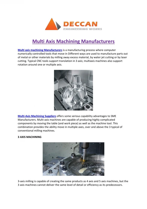
Download
1 / 12
120 likes | 292 Views
Generic Simulation Approach for Multi-Axis Machining, Part 2:. Model Calibration and Feed Rate Scheduling Journal of Manufacturing Science and Engineering (August 2002) T. Bailey M. A. Elbestawi T. I. El-Wardany P. Fitzpartick Presented By: Levi Haupt 30 July 2014 ME 482. Overview.

E N D
Generic Simulation Approach for Multi-Axis Machining, Part 2: Model Calibration and Feed Rate Scheduling Journal of Manufacturing Science and Engineering (August 2002) T. Bailey M. A. Elbestawi T. I. El-Wardany P. Fitzpartick Presented By: Levi Haupt 30 July 2014 ME 482
Overview • Development of Least-Squares Fit model of multi-axis machining • Process optimization for specified parameters • Determine instantaneous feed rate based on load prediction model • Improve machining time while maintaining geometric specifications
Outline • Purpose of Paper • Methodology • Results • Conclusion
Purpose of Paper • Develop methodology to simulate machining of complex surfaces (Calibrating Coefficients) • Validate simulated results with experimental data • Demonstrate results through airfoil case study
Methodology • Model Calibration • Calibration of cutting for coefficients • Formulate force model to separate cutting force coefficients and geometric factors • Cutting test performed varying cutting speed, feed rate, axial depth of cut, radial width of cut, from test cutting force data obtained • Coefficients found from test data utilizing Least-Square Fit Regression • Feed per tooth coefficients found from constant feed rate coefficient • Average Coefficients found from tooth coefficients
Methodology Calibration Results: Solid line coefficient from step 4 Third graphs comparison of coefficients
Methodology • Feed Rate Scheduling • Variation of feed rate will prevent tool damage (chatter) and improve surface finish • Productivity traditionally decreased to improve process parameters • Process constraints: shank and tooth breakage, chatter limits, surface dimensional error • Utilizing chip load or force constraints will satisfy all other constraints • Roughing: Max force constraint • Finishing: Max chip load constraint • Feed rate determined for instantaneous cut geometry and forces based on constraints
Results • Average Coefficient model predictions of loads within 5% of experimental data • Case Study: “Airfoil like surface” • 19mm solid carbide ball end mill • 30 roughing passes Roughing Stages Surface Profile
Results Approximately 30% reduction in machine time with implemented feed rate schedule methodology No feed schedule: 293 seconds Feed Schedule: 210 seconds
Conclusion • Successful analytical model • Demonstrated accurate force predictions • Within 5% of experimental data • Versatile for complex machining surfaces • Can also be used to predict static and dynamic tool deflections, dynamic cutting forces • Technical Advancements • Improved model accuracy • Improve feed rate scheduling • 30% reduction of machining time • Methodology implemented in industry • Possible limitations • Excitation of dynamics in feed rate controller system • Parallel research was conducted (source 17)
Questions? Happy Halloween!!