Download
1 / 27
270 likes | 369 Views
System Definition Review AAE 451. Team GoldJet. Andrew Mizener Diane Barney Jon Coughlin Jared Scheid Mark Glover Michael Coffey Donald Barrett Eric Smith Kevin Lincoln. Mission Statement.

E N D
System Definition ReviewAAE 451 Team GoldJet Andrew Mizener Diane Barney Jon Coughlin Jared Scheid Mark Glover Michael Coffey Donald Barrett Eric Smith Kevin Lincoln
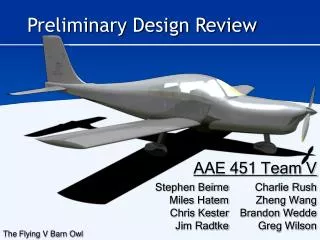
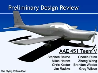
Mission Statement To design a profitable, supersonic aircraft capable of Trans-Pacific travel to meet the needs of airlines and their passengers around the world.
Major Design Requirements Trans-Pacific Range: Longer range increases available routes High Cruise Speed : Makes shorter trip times and allows for more legs per day Good Cruise Efficiency: Lowers the cost of fuel and the max gross weight
Design Mission • Los Angeles (LAX) – Shanghai (PDG) • Range: 5,650 nautical miles
Morphological Matrix To assist Pugh’s Method and Concept Selection Listed design categories and all options
First Concepts • Four Concepts Chosen, along with Datum • Showed immediate narrowing of possible ideas in some categories • Two wing planforms • Two fuselage types • One landing gear style
Pugh’s Method • Two rounds • First against the Datum • Second against one of our first designs (Concept 2) • Second round shown • Some narrowing of categories as process went along
Condensed Concepts • Taking results of Pugh’s Method, two concepts emerged for further study • One based around a Double-Delta wing • Result of min/maxing DD concepts • Three Design Choices to make • Engine Location, Canards, and Tail Configuration • One based around a Joined Wing
1x1 Seating Layout • 1x1 Seating Configuration • Design allows for long slender body, reducing drag • Carry-on baggage stowed next to passenger • Allows for easier in flight access • Up to two carry-on bags can be carried due to increased space
1x1 Top View Galley Lav Lav Entry Door Length 90 feet Lavatories positioned at the front and rear of the cabin Galley located forward
1x1 Cross-Section Carry On Storage Diameter: 10 ft Aisle Width: 26 inches Aisle Height: 76 inches Seat Pitch: 40 inches
2x2 Seating Layout 2x2 Seating Configuration Shorter fuselage length, enabling more radical Sears-Haack shaping Carry-on baggage stored overhead
2x2 Top View Lav Galley Lav Entry Door Length 54 feet Lavatories located aft Galley located aft
2x2 Cross-Section Diameter: 11 feet 8 inches Aisle Width: 26 inches Aisle Height: 76 inches Seat Pitch: 40 inches
Performance Constraints • 5 main performance constraints identified: • Steady, Level Flight • M = 1.8, h = 45,000 ft • Subsonic 2g Manuever, • 250kts , h = 10,000 ft • Takeoff Ground Roll • 5400 ft, h = 1,000 ft, +15° Hot Day • Landing Ground Roll • 5400 ft, h = 1,000 ft, +15° Hot Day • 3% Second Segment Climb Gradient (4 engines) • Above h = 1,000 ft, +15° Hot Day
Constraint Assumptions • Landing • αrev = 0.2 • β = 1 • CL,max,Land= 1.5 • μ = 0.2 (wet concrete/asphalt) • Field Length = 10000 ft • sLand = 6000 ft • 2nd Segment Climb • CD0, AR, ΛLE • Four Engines (3% CGR) • CL,max,TO = 1.2 • eTO= 0.525 • Cruise • Lapse Rate = 0.678 (ρ ratio) • CD0 = 0.018 • AR = 2 • ΛLE = 45° • dmax = 11.75 ft • l = 180 ft • CDw = 0.00644 • Subsonic Maneuver • CD0 & AR • e = 0.7 • Takeoff • β = 1 • CL,max,TO = 1.2 • Field Length = 10000 ft • sTO = 6000 ft
Current Sizing Method Based upon calculating the fuel fraction as described in Raymer Empty weight fraction based upon historical aircraft data Technical Factor of 0.95 for advanced materials
Results • Design Variables • Mission Range: 5650 nmi • Aspect Ratio: 2 • Wing Loading: 125 lb/ft2 • Thrust to Weight: 0.375 • Maximum Mach Number: 2 • Cruise Mach Number: 1.8 • SFC: 0.8 /hr • Resulting Weights • W0=341,000 lbs • We=126,000 lbs • Wf =206,000 lbs • Wing Area • S=2,700 ft2
Sonic Boom Prediction • Based upon Carlson • “Simplified Sonic-Boom Prediction” • Uses a series of non-linear factors based on altitude and shape • Determines • Overpressure • Duration
Baseline Overpressure • Cruise Condition • M=1.8 • Alt = 45,000 ft • Results • Overpressure: 1.66 lb/ft2 • Duration: 0.155 seconds
Double Delta Wing Planform Raked Wingtips Low wing Blended Wing/Circular Fuselage Tricycle Landing Gear 2x2 Cabin Canard, Tail,Engine Locationto be optimized Double Delta Configuration Rough DD with Canards and No Tail DD with no canards and Conventional Tail
Joined Wing Configuration Joined Wing Planform Canards Engines podded and aft on fuselage Circular Fuselage Tricycle Landing Gear 1x1 Cabin
Next Steps Preliminary analysis Main concept selection Detailed analysis Final layout/configuration selection
Concept Analysis Double Delta Engine placement Drag effects Ground clearance Maintenance cost Landing gear size/weight Noise shielding Canards vs. horizontal tail Drag varying with surface size Canard issues at take-off Airport compatibility Fuselage/wing blending • Joined Wing • Wing structure • Complexity • Fuel storage • Weight savings • Aerodynamic performance
Analysis Topics • Cost Model • Systems • Airport gate compatibility • Ground clearance • Control • Stability • Static Margin • CG travel • Optimization • Detailed sizing • Carpet plots • Aerodynamics • Cross-sectional area plot • Wave drag • Induced drag • Boom forming • Structures • Strength analysis • Weight and weight distribution • Propulsion • Engine model • Engine choice