COMPONENT DIAGRAM
COMPONENT DIAGRAM. Component Diagram Component diagram menggambarkan struktur dan hubungan antar komponen piranti lunak, termasuk ketergantungan ( dependency ) di antaranya. Komponen piranti lunak adalah modul berisi code , baik berisi source code maupun binary code , baik

COMPONENT DIAGRAM
E N D
Presentation Transcript
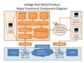
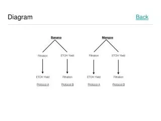
Component Diagram Component diagram menggambarkan struktur dan hubungan antar komponen piranti lunak, termasuk ketergantungan (dependency) di antaranya. Komponen piranti lunak adalah modul berisi code, baik berisi source code maupun binary code, baik library maupun executable, baik yang muncul pada compile time, link time, maupun run time. Umumnya komponen terbentuk dari beberapa class dan/atau package, tapi dapat juga dari komponen-komponen yang lebih kecil. Komponen dapat juga berupa interface, yaitu kumpulan layanan yang disediakan sebuah komponen untuk komponen lain. Contoh component diagram:
Component Diagram • Menggambarkan alokasi semua class dan object kedalam komponen dalam desain fisik system software, termasuk pengaturan dan kebergantungan antar komponen software • Component dapat terdiri dari • logical component, seperti business component, process component, dll • Physical component (software arsitektur) , seperti Com+, dot NET,CORBA, dll • Component digambarkan • dengan bentuk pada UML versi 1.*: • Pada UML versi 2 digambarkan dengan bentuk • atau atau atau • Stereotypes yang dapat digambarkan pada bentuk component • <<application>>,kumpulan aplikasi system • <<executable>>,component yang jalan di client • <<file>>, data file<<infrastructure>>, technical component didalam system<<source code>>, source file • <<table>>, table data dalam sebuah database<<UI>>, User interface (screen, pages, report) • dll <<database>> <<document>> <<library>> <<web service>> <<XML DTD>>
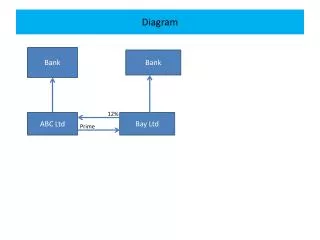
Component Diagram • Dependencies • dimodelkan dengan garis terputus dengan panah terbuka • gambarkan dependencies dari kiri ke kanan • Contoh: • <<ASP>> Source Code bergantung pada • <<database>> MySQL • Dimungkinkan sebuah component dependencies pada interfaces component lainnya • Contoh: • Inheritance • inheriting/child component diletakkan dibawah parent component, dengan arah panah menuju ke parent component • dimodelkan dengan garis dengan panah tertutup • Contoh:
Interfaces - Component Diagram • Interfaces adalah kumpulan >=1 methode dan >=0 attribute yang dapat dipakai pada class tanpa menjadi behavior suatu class. • Jenis interface ada 2 macam yaitu : • Provide, digambarkan dengan bentuk lollipop • Pada UML 1.* bisa juga digambarkan dengan garis terputus dengan panah tertutup • Required, digambarkan dengan bentuk socket • Penggambaran interfaces dapat juga dilakukan dengan menambah bagian component seperti contoh dibawah ini • Bentuk grafik
Component Diagram • port • adalah bentuk object yang menjelaskan interaksi antara object dan lingkungannya • digambarkan sebagai kotak kecil di pinggiran component • Assembly connector • Penghubung antara 2/lebih component dimana sebuah/beberapa component provides interfaces dan component lain required interfaces • Digambarkan dengan gabungan bentuk interfaces • contoh: