Download
1 / 48
520 likes | 786 Views
Solar Powered Tracker and Charging Device. Sponsored by: Progress Energy Group 12: Diijon Gumbs James Lillie Kaniel Martin. Goals and Objectives.

E N D
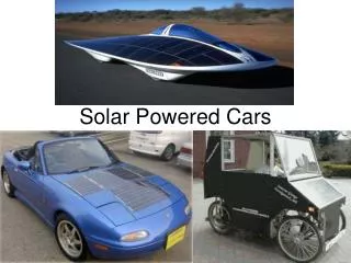
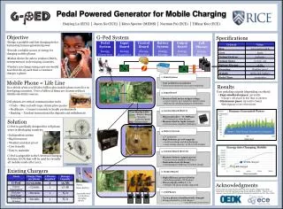
Solar Powered Tracker and Charging Device Sponsored by: Progress Energy Group 12: DiijonGumbs James Lillie Kaniel Martin
Goals and Objectives • To build a mobile device to track sunlight and use it for conversion to energy for charging batteries (car and normal sized battery). • Needs to be cost efficient • Needs to be able withstand different types of weather conditions. • Track the most amount of sunlight through actuation.
Specifications and Requirements • Solar panels • Weather Resistant • Produce 40 W of power • Have 50% efficiency • Frame • Weather Resistant • 360 degree horizontal rotation • 120 degrees vertical rotation • Total Weight No larger than 30 pounds • Rotating Frame No larger than 15 pounds • Dissipate heat • Voltage Regulator • Used to charge 5-12 Volt batteries • Have about 85% power efficiency • Stepper Motors • Use 0.5-1.5 amps • Can freely move 5pounds
Specifications and Requirements Continued • Microcontroller • Can at least receive 8 inputs • Has at least 10 output ports • Can handle both analog and digital I/O • Has Pulse Width Modulation • Batteries • Rechargeable • 15-20V • Voltage Sensors • Can read voltage from 0.1 -50V • Display • Can display our four output criteria • Can support at least a 5V input • Servo Motor • Operates on 5V • 100 degree turning radius
Block Diagram of Design Solar Panels Batteries Regulator LCD Display Photo Sensors Voltage Sensors Microcontroller Motor Controller Motors
Solar Panels, Microcontroller, Voltage Regulator, Batteries Kaniel Martin
Arduino Mega 2560 • 5V operating voltage • 6-20V input • 54 digital I/O pins • 14 PWM outputs • 16 analog Input Pins • 256 KB Flash Memory • 8 KB SRAM • 16 MHz Clock Speed
LM358 Voltage Regulator • 35 Max Voltage
Batteries 19V Battery used to power the board, and LCD 16 V Battery used to power the motors 12 V and AA Batteries used for charging
Alkaline Batteries • Rechargeable • 80% efficiency • Up to 50 times the lifetime of the non-rechargeable variety • 50 – 500 cycles • Easy to predict charge • Non Rechargeable • 95% efficiency • Less than 5 year lifespan • Harmful to the environment • Cheap!!
Nickel Cadmium • 70%-90% efficient • Lasts up to 5 years • 1500 cycles • Charge rate of C/10 • Lose charge quickly • Toxic! • Average Cost
Lithium Ion • High initial voltage • Have a high charge level • Become very hot • Excellent performance initially but declines with time. • Very expensive • 1200 cycles • 2-3 years • 5%- 10% discharge rate
Lead Acid Batteries • 70% – 80% efficient • Lasts 5-8 years • 500-800 cycles • Charge Rate of C/8 • Low Cost • Easily Recycled • Large Array of sizes and voltage levels
Problems • Deciding on whether to use one battery to power the whole project, or to designate a battery for each component. • How to deal with the major fluxuations in voltage from sunlight to the circuit design and overall efficiency. • Not only learning more about the different programming codes needed for our design, but the integration of them as well.
LCD Display, Solar Sensors, Voltage Sensors DiijonGumbs
LCD Display • We need a display to show the proper criteria in relation to the project. • These criteria include: power efficiency, current, voltage, and battery life. • This criteria must be produced on the display through a percentage or as a unit of measurement. • Memory storage will be an important element in determining what type of display chosen.
Hitachi HD44780 Display • Usage of ASCII symbols through binary to read to the display. • Cheap in cost • Dimensions: 98.0x60.0x15.0 mm • 16 ports to be used • Components • 20 characters by 4 line display • White characters with a blue background and backlight display • 7 pin GPIO pin usage for 4-bit mode and 11 pin GPIO pin usage for 8-bit mode • 5V DC operation • Wide viewing angle and high contrast • +5V DC LED backlight
HD44780 LCD Display • For this project we will be only using a limited amount of ports and not all of them for our displaying of data. • Will be employing 4-bit mode operation • 16-bit male header needs to be put on through a soldering process before being used with breadboard.
Viewing our results on LCD Display • Backlight will be incorporated when weather conditions hinder viewing ability. • We need to also change the contrast by using a 10k potentiometer connected to the contrast port (port 3).
Solar Sensing • Sense how much sunlight is being shone. • Usually most solar sensing is used through the use of photodiodes or photoresistors. • Must be used through devising a circuit.
Photoresistors • Same as photodiodes except they don’t react to sunlight well. • Use simple voltage divider circuit to get readings. • Best decision when it comes to our project. • Looked into the VT400 Perkin Elmer series. • Three main types: Indium Antimonide, Silicon, and Cadmium Sulfide.
Photoresistors Continued • Our choice was the Cadmium Sulfide type photoresistor from Adafruit (light: 5-10K; dark: 200K). • Will be using with a 1K resistor to realize voltage reading circuit with the 5V input connected to microcontroller port. Other portion will be connected to analog pin on arduino board. • Can use a 10K resistor instead, but it will hurt our readings at bright levels of light.
Voltage Sensing • Looked into many types of panel sensors. • One approach: we were looking into using a voltmeter to incorporate into our finalized circuit through the soldering of the contacts onto a finalized circuit. • Final decision: • Simple voltage divider circuit to read the voltage as we used for the light sensing. • similar to photoresistor circuit
Circuit Implementation • Using a breadboard kit to conglomerate LCD Display, voltage dividers with the photoresistors will make up our circuit.
Problems • LCD Display • Have to learn more about the use of the codes for the ASCII characters (display). • Looking into how to incorporate display with the main microcontroller to show the accuracy of the results. • Solar Sensor (Photoresistor) • Finding out if the resistor value chosen will indeed show the brightness of the light or miscalculate the results. • Voltage Sensor • How to make sure the readings were read precisely with accuracy (noise).
Frame, Motors, & Motor Controllers James Lillie
Frame • Required to house electrical components as well as allow mounting locations for solar panels • Allows two Panels to be mounted one facing up one facing down • Has reflective surface for downward facing solar panel • Allows for a locking mechanisms • Water Resistant
Panel Rotation • 360 Degrees of Horizontal Rotation • 120 Degrees of Vertical Rotation • DC Motors, Stepper Motors, Servos, Linear Actuators • Gear Reducing Ratio for higher torque • Accurate Rotational Speed
Servo Motor • Used as a locking mechanism • Can operate off of the Arduino Mega 2560 • Can operate on 5V power source • Rotation Range of at least 60 degrees
Hitec 322 Standard Servo Motor Torque: 41.66 - 51.38 oz*in Voltage: 4.8V - 6V Turning Range: 100-200 Degrees
Stepper Motor • Needed to turn frame. • Low power consumption (less than 2amps) • High Torque • Able to output enough force to rotate a static 15lb disk
Bipolar Stepper Motor • Step Angle: 1.8 degrees • 2 Phase • Rated Voltage 12-15.4 Volts • Rated Current .28-.33 Amps • Holding Torque 2.4kg*cm • Detent Torque 120g*cm
Motor Controller • Needed to drive two stepper motors • Voltage rating of at least 16 volts • Easily interfaced with micro-controller • Has quarter, half, and full step capabilites • Has Sleep Mode for Power Saving
Eazy Stepper V4 • Drives one Bipolar Stepper Motor • Compatible with 4,6,or 8 wire Motors • Power Supply Range of 7-30 Volts • Adjustable Current From 0.15-0.75 Amps • Sleep Mode
Problems Frame Rotating Location • Frame cannot rotate more than 360 degrees to stop the tangling of wires.