Download
1 / 53
770 likes | 1.22k Views
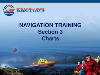
NAVIGATION TRAINING Section 8 Position Lines and Fixes. Table of Contents. Section 1 Types of Navigation Section 2 Terrestial Coordinates Section 3 Charts Section 4 Compass Section 5 Nautical Publications Section 6 Navigational Aids. Table of Contents. Section 7 Buoyage

E N D
NAVIGATION TRAINING Section 8 Position Lines and Fixes
Table of Contents • Section 1 Types of Navigation • Section 2 Terrestial Coordinates • Section 3 Charts • Section 4 Compass • Section 5 Nautical Publications • Section 6 Navigational Aids
Table of Contents • Section 7 Buoyage • Section 8 Position Lines and Fixes • Section 9 Tides • Section 10 Currents • Section 11 Weather
Position Lines • Position Lines (P/L) - A single observation that does not establish a fix, but does mean that ship’s position is somewhere along that line. • Label - After the position line is drawn from a charted object, a four digit time must be written above and parallel to the position line.
Position Lines • All Compass bearings that are to be plotted on the chart, must be corrected to True Bearings, allowing for any compass error, including deviation and variation, before plotting. • All True bearings/ courses taken from the chart, must be corrected for any compass error to obtain Compass Bearings/compass before use on radar or vessel’s magnetic compass.
Sources of Position Lines • A visual position line can be taken, using charted fixed navigational aids such as tanks, water towers, church steeples, spires, radio and TV towers, day marks, fixed navigation lights, flagpoles, or tangents to points of land. • In general fixing off floating objects, especially buoys, should be avoided, if there are fixed charted objects available.
Visual Position Line 1000
Position Line Measurement • Visual Bearings can be measured in: 1. Degrees Relative ( # # # 0R ) 2. Degrees per Gyro Compass ( # # # ºG ) 3. Degrees Magnetic ( # # # 0M ) • The navigator must convert any of these types of bearings to True before they can be plotted on the chart. Degrees True ( # # # 0T)
Plotting and Labeling a Fix • Fix - The point where two or more position lines, taken at the same time, cross. This indicates the ship’s position on the chart. • Label - Use the four digit time next to the fix,it should be parallel to the bottom of the chart. The times of the individual position lines are not written.
Visual Position Fix 1 Compass bearing of Abode Island bearing 009°Compass, deviation 1ºW, variation 23ºE, gives 030 º True Bearing
Visual Position Fix 2 Compass bearing of Grebe Island Light bearing 058 º Compass, deviation 1ºW, variation 23ºE, gives 080 º True Bearing
Visual Position Fix 3 Compass bearing of Pt. Atkinson Light bearing 098ºCompass, deviation 1ºW, variation 23º E, gives True Bearing of 120 º T
Visual Position Fix 4 Insert fix circle on intersection of position lines, and time of fix 1230
Cocked Hats • In a perfect world, with due allowance made for compass error, the three position lines will cross at one point. • However depending on the speed of the vessel, the proximity of the object from which a vessel is being fixed, and the accuracy of the bearing when taken, and other factors, it is far more likely that a cocked hat will be obtained. • The larger the cocked hat, the larger an error on one, two or all of the position lines is likely to be.
Cocked Hat In this example there is an error of 3ºE on the compass bearing of Point Atkinson Light and a cocked hat is formed. 1230
Cocked Hats • Where a plotted position is a cocked hat, and there is no obvious error (such as in calculation), it should be generally assumed the position of the vessel is the point in the cocked hat closest to the nearest danger. • Another position should be taken a soon as convenient to check on the position.An
Reducing Errors • When taking distances or ranges, always take the ranges ahead or astern first, to minimise errors (as these ranges will change quickest with the speed of the vessel) before taking ranges on the beam. • When taking compass bearings, always take the bearings on the beam first, to minimise errors (as these bearings will change quickest with the speed of the vessel) before taking bearings ahead or astern.
Radar Fixes • Radar bearings are subject to compass error. • Therefore the best way to obtain a fix by radar, is to take three radar distances off charted and identified objects.
Radar Position 1 Using radar: Grebe Is Electronic Bearing Marker showing 058 º M Variable Range Marker showing 0.82’
Radar Position 2 From radar, plot position circle: Grebe Is Distance 0.49 nm
Radar Position 3 Grebe Is Range 0.82’ A second range of 0.93’ off Eagle Is. would give fix Mark fix position and time. Best fix would be have third range. 1000
Radar Position 4 Radar bearing of Grebe Is. is 058 º compass Deviation 1ºW Variation 23ºE True Bearing 080 ºT which confirms ranges 1000
Electronic Position • The GPS can give an accurate electronic position. • First check that the GPS information is live, and not on Dead Reckoning (which GPS reverts to with certain faults). • Also check that the HDOP figure is low - 1 is best.
Electronic Position 1 Note down Latitude and Longitude 49º 20.38’N 123º 17.23’W
Electronic Position 2 Plot Latitude and Longitude 49º 20.38’N 123º 17.23’W
Electronic Position 3 Insert fix symbol, and time 1000
Transits • Transits are the most accurate type of position line, when two charted objects line up. • Transits are one of the most valuable tools when close to dangers or the land. • Some transits are man made (intentional) and others are natural (coincidental).
Transits • The main benefits of transits are: 1. There is no compass deviation or variation. 2. They can be used when the vessel's motion interferes with the use of a compass. 3. They are instantaneous and can be monitored continuously. 4.They occur frequently when in confined waters.
Transits • Good transit - Beacon in line with lighthouse
Transits • Poor transit - Buoy in line with end of land. This may be inaccurate due to land changing due to tidal height and the buoy being set by tidal stream or current.
Transits 0945 A transit can give either a position line, or as shown, a heading to steer on from the northwest, before altering to about 045°T into Fishermans Cove
LabelingFixes Symbol Type Meaning Accurate Visual Fix Fix Fix DR EP Accurate Fix obtained by electronic means Dead reckon position, advanced from previous fix. Estimated position. Most probable positionof ship.
Dead Reckoning • Dead Reckoning is the process of determining a ship’s approximate position by applying, from its last known position, a vector or a series of consecutive vectors representing the true courses steered and the distances run as determined by the ship’s speed and time, without considering the effects of wind and current. • From a known ship’s position, predicted future positions are plotted.
Dead Reckoning DR 1245 From ship’s known position at 1230, a future position is plotted for 1245, knowing vessel’s course and speed. 1230
Dead Reckoning • Dead Reckoning is derived from DEDUCED, or DED, reckoning which was the process by which a vessel’s position was computed trigonometrically in relation to a known point of departure.
Estimated Position EP 1245 From ship’s known position at 1230, a future position is plotted for 1245, knowing vessel’s course and speed, and allowing for set and drift of tide. 1230
Parallel Indexing • Parallel indexing is using the radar to monitor the track of a vessel along a preplanned course, maintaining a distance off a known charted object. • Where using a magnetic compass input to a radar, the true bearing will have to be corrected for variation and deviation before setting the Electronic Bearing Marker.
Parallel Indexing Find a radar conspicuous object on the chart. Draw a line parallel to the required course touching the object. Measure the distance between the course line and the parallel index line. That is the Cross Index range. 015ºT CIR 0.32’
ParallelIndexing Course 017°C VRM 0.18nm EBL 017°C Offset and set up the Variable Range Marker to the distance off a conspicuous point of land that is required, and set the Electronic Bearing Marker to the required compass course.
Parallel Indexing Course 017°C VRM 0.18nm EBL 017°C The VRM should run up the EBL if the vessel is staying on track.