Download
1 / 31
330 likes | 719 Views
Fading multipath radio channels. Narrowband channel modelling Wideband channel modelling Wideband WSSUS channel (functions, variables & distributions). Low-pass equivalent (LPE) signal. RF carrier frequency. Real-valued RF signal. Complex-valued LPE signal.

E N D
Fading multipath radio channels • Narrowband channel modelling • Wideband channel modelling • Wideband WSSUS channel • (functions, variables & distributions)
Low-pass equivalent (LPE) signal RF carrier frequency Real-valued RF signal Complex-valued LPE signal In-phase signal component Quadrature component
Spectrum characteristics of LPE signal magnitude Real-valued time domain signal (e.g. RF signal) 0 f phase Signal spectrum is Hermitian 0 f Complex-valued LPE time domain signal Signal spectrum is not Hermitian
Radio channel modelling Narrowband modelling Wideband modelling Calculation of path loss e.g. taking into account - free space loss - reflections - diffraction - scattering Deterministic models (e.g. ray tracing, playback modelling) Stochastical models (e.g. WSSUS) Basic problem: signal fading Basic problem: signal dispersion
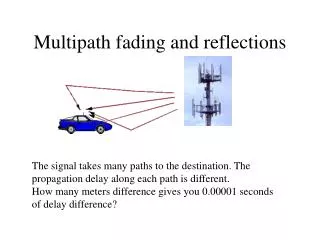
Signal fading in a narrowband channel magnitude of complex-valued LPE radio signal distance propagation paths fade <=> signal replicas received via different propagation paths cause destructive interference Tx Rx
Fading: illustration in complex plane Received signal in vector form: resultant (= summation result) of “propagation path vectors” quadrature phase component path delays are not important Rx Tx in-phase component Wideband channel modelling: in addition to magnitudes and phases, also path delays are important.
Propagation mechanisms A: free space B: reflection C: diffraction D: scattering A: free space B: reflection C: diffraction D: scattering reflection: object is large compared to wavelength scattering: object is small or its surface irregular
Countermeasures: narrowband fading Diversity (transmitting the same signal at different frequencies, at different times, or to/from different antennas) - will be investigated in later lectures - wideband channels => multipath diversity Interleaving (efficient when a fade affects many bits or symbols at a time), frequency hopping Forward Error Correction (FEC, uses large overhead) Automatic Repeat reQuest schemes (ARQ, cannot be used for transmission of real-time information)
Bit interleaving Transmitter Channel Receiver Bits are interleaved ... Fading affects many adjacent bits After de-interleaving of bits, bit errors are spread! ... and will be de-interleaved in the receiver Bit errors in the receiver (better for FEC)
Channel Impulse Response (CIR) delay spread Tm Channel is assumed linear! h(,t) time t Channel presented in delay / time domain (3 other ways possible!) delay zero excess delay
CIR of a wideband fading channel The CIR consists of L resolvable propagation paths path attenuation path phase path delay LOS path
Received multipath signal Transmitted signal: complex symbol pulse waveform Received signal:
Received multipath signal The received multipath signal is the sum of L attenuated, phase shifted and delayed replicas of the transmitted signal s(t) T : Tm Normalized delay spread D = Tm / T
Received multipath signal The normalized delay spread is an important quantity. When D << 1, the channel is - narrowband - frequency-nonselective - flat and there is no intersymbol interference (ISI). When D approaches or exceeds unity, the channel is - wideband - frequency selective - time dispersive Important feature has many names!
BER vs. S/N performance In a Gaussian channel (no fading) BER <=> Q(S/N) erfc(S/N) Typical BER vs. S/N curves BER Frequency-selective channel (no equalization) Gaussian channel (no fading) Flat fading channel S/N
BER vs. S/N performance Flat fading (Proakis 7.3): z= signal power level Typical BER vs. S/N curves BER Frequency-selective channel (no equalization) Gaussian channel (no fading) Flat fading channel S/N
BER vs. S/N performance Frequency selective fading <=> irreducible BER floor Typical BER vs. S/N curves BER Frequency-selective channel (no equalization) Gaussian channel (no fading) Flat fading channel S/N
BER vs. S/N performance Diversity (e.g. multipath diversity) <=> improved performance Typical BER vs. S/N curves BER Gaussian channel (no fading) Frequency-selective channel (with equalization) Flat fading channel S/N
Time-variant transfer function Time-variant CIR: Time-variant transfer function (frequency response): In a narrowband channel this reduces to:
Example: two-ray channel (L = 2) At certain frequencies the two terms add constructively (destructively) and we obtain: f
Deterministic channel functions (Inverse) Fourier transform Time-variant impulse response Time- variant transfer function Doppler- variant impulse response Doppler-variant transfer function
Stochastical (WSSUS) channel functions Channel intensity profile Tm Td Frequency time correlation function Scattering function Channel Doppler spectrum Bm Bd
Stochastical (WSSUS) channel variables Tm Maximum delay spread: Maximum delay spread may be defined in several ways. For this reason, the RMS delay spread is often used instead: Tm
Stochastical (WSSUS) channel variables Coherence bandwidth of channel: Bm f 0 Implication of coherence bandwidth: If two sinusoids (frequencies) are spaced much less apart than Bm , their fading performance issimilar. If the frequency separation is much larger than Bm , their fading performance isdifferent.
Stochastical (WSSUS) channel variables Bd Maximum Doppler spread: The Doppler spectrum is often U-shaped (like in the figure on the right). The reason for this behaviour is the relationship (see next slide): 0 Bd Task: calculate p(n) for the case where p(a) = 1/2p (angle of arrival is uniformly distributed between 0 and 2p).
Physical interpretation of Doppler shift V arriving path direction of receiver movement Rx Doppler frequency shift V = speed of receiver l = RF wavelength Angle of arrival of arriving path with respect to direction of movement Maximum Doppler shift
Delay - Doppler spread of channel delay L = 12 components in delay-Doppler domain 0 Doppler shift Bd
Fading distributions (Rayleigh) In a flat fading channel, the (time-variant) CIR reduces to a (time-variant) complex channel coefficient: When the quadrature components of the channel coefficient are independently and Gaussian distributed, we get: Rayleigh distribution Uniform distribution
Fading distributions (Rice) In case there is a strong (e.g., LOS) multipath component in addition to the complex Gaussian component, we obtain: From the joint (magnitude and phase) pdf we can derive: Modified Bessel function of first kind and order zero Rice distribution
Representation in complex plane Complex Gaussian distribution is centered at the origin of the complex plane => magnitude is Rayleigh distributed, the probability of a deep fade is larger than in the Rician case Complex Gaussian distribution is centered around the “strong path” => magnitude is Rice distributed, probability of deep fade isextremely small iy iy x x Bell-shaped function
Countermeasures: wideband systems Equalization (in TDMA systems) - linear equalization - Decision Feedback Equalization (DFE) - Maximum Likelihood Sequence Estimation (MLSE) using Viterbi algorithm Rake receiver schemes (in DS-CDMA systems) Sufficient number of subcarriers and sufficiently long guard interval (in OFDM or multicarrier systems) Interleaving, FEC, ARQ etc. may also be helpful in wideband systems.