Download
1 / 62
620 likes | 793 Views
Assemblers. System Software by Leland L. Beck Chapter 2. Role of Assembler. Assembler. Object Code. Linker. Source Program. Executable Code. Loader. Chapter 2 -- Outline. Basic Assembler Functions Machine-dependent Assembler Features Machine-independent Assembler Features

E N D
Assemblers System Software by Leland L. Beck Chapter 2
Role of Assembler Assembler Object Code Linker Source Program Executable Code Loader
Chapter 2 -- Outline • Basic Assembler Functions • Machine-dependent Assembler Features • Machine-independent Assembler Features • Assembler Design Options
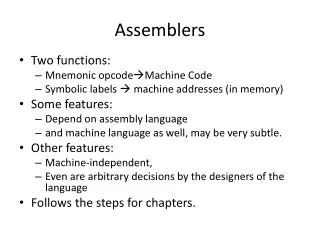
Introduction to Assemblers • Fundamental functions • translating mnemonic operation codes to their machine language equivalents • assigning machine addresses to symbolic labels • Machine dependency • different machine instruction formats and codes
Example Program (Fig. 2.1) • Purpose • reads records from input device (code F1) • copies them to output device (code 05) • at the end of the file, writes EOF on the output device, then RSUB to the operating system
Example Program (Fig. 2.1) • Data transfer (RD, WD) • a buffer is used to store record • buffering is necessary for different I/O rates • the end of each record is marked with a null character (0016) • the end of the file is indicated by a zero-length record • Subroutines (JSUB, RSUB) • RDREC, WRREC • save link register first before nested jump
Assembler Directives • Pseudo-Instructions • Not translated into machine instructions • Providing information to the assembler • Basic assembler directives • START • END • BYTE • WORD • RESB • RESW
Assembler’s functions • Convert mnemonic operation codes to their machine language equivalents • Convert symbolic operands to their equivalent machine addresses • Build the machine instructions in the proper format • Convert the data constants to internal machine representations • Write the object program and the assembly listing
Example of Instruction Assemble • Forward reference STCH BUFFER,X 549039 (54)16 1 (001)2 (039)16
Difficulties: Forward Reference • Forward reference: reference to a label that is defined later in the program. LocLabelOperatorOperand 1000 FIRST STL RETADR 1003 CLOOP JSUB RDREC … … … … … 1012 J CLOOP … … … … … 1033 RETADR RESW 1
Two Pass Assembler • Pass 1 • Assign addresses to all statements in the program • Save the values assigned to all labels for use in Pass 2 • Perform some processing of assembler directives • Pass 2 • Assemble instructions • Generate data values defined by BYTE, WORD • Perform processing of assembler directives not done in Pass 1 • Write the object program and the assembly listing
Intermediate file Two Pass Assembler • Read from input line • LABEL, OPCODE, OPERAND Source program Object codes Pass 1 Pass 2 OPTAB SYMTAB SYMTAB
Data Structures • Operation Code Table (OPTAB) • Symbol Table (SYMTAB) • Location Counter(LOCCTR)
OPTAB (operation code table) • Content • menmonic, machine code (instruction format, length) etc. • Characteristic • static table • Implementation • array or hash table, easy for search
SYMTAB (symbol table) • Content • label name, value, flag, (type, length) etc. • Characteristic • dynamic table (insert, delete, search) • Implementation • hash table, non-random keys, hashing function COPY 1000 FIRST 1000 CLOOP 1003 ENDFIL 1015 EOF 1024 THREE 102D ZERO 1030 RETADR 1033 LENGTH 1036 BUFFER 1039 RDREC 2039
Object Program • Header Col. 1 H Col. 2~7 Program name Col. 8~13 Starting address (hex) Col. 14-19 Length of object program in bytes (hex) • Text Col.1 T Col.2~7 Starting address in this record (hex) Col. 8~9 Length of object code in this record in bytes (hex) Col. 10~69 Object code (69-10+1)/6=10 instructions • End Col.1 E Col.2~7 Address of first executable instruction (hex) (END program_name)
Fig. 2.3 H COPY 001000 00107A T 001000 1E 141033 482039 001036 281030 301015 482061 ... T 00101E 15 0C1036 482061 081044 4C0000 454F46 000003 000000 T 002039 1E 041030 001030 E0205D 30203F D8205D 281030 … T 002057 1C 101036 4C0000 F1 001000 041030 E02079 302064 … T 002073 07 382064 4C0000 05 E 001000
Homework #1 SUM START 4000 FIRST LDX ZERO LDA ZERO LOOP ADD TABLE,X TIX COUNT JLT LOOP STA TOTAL RSUB TABLE RESW 2000 COUNT RESW 1 ZERO WORD 0 TOTAL RESW 1 END FIRST End of Sec 2-1
Assembler Design • Machine Dependent Assembler Features • instruction formats and addressing modes • program relocation • Machine Independent Assembler Features • literals • symbol-defining statements • expressions • program blocks • control sections and program linking
Machine-dependent Assembler Features Sec. 2-2 Instruction formats and addressing modes Program relocation
Instruction Format and Addressing Mode • SIC/XE • PC-relative or Base-relative addressing: op m • Indirect addressing: op @m • Immediate addressing: op #c • Extended format: +op m • Index addressing: op m,x • register-to-register instructions • larger memory -> multi-programming (program allocation) • Example program • Figure 2.5
Translation • Register translation • register name (A, X, L, B, S, T, F, PC, SW) and their values (0,1, 2, 3, 4, 5, 6, 8, 9) • preloaded in SYMTAB • Address translation • Most register-memory instructions use program counter relative or base relative addressing • Format 3: 12-bit address field • base-relative: 0~4095 • pc-relative: -2048~2047 • Format 4: 20-bit address field
PC-Relative Addressing Modes • PC-relative • 10 0000 FIRST STL RETADR 17202D (14)16 1 1 0 0 1 0 (02D) 16 • displacement= RETADR - PC = 30-3 = 2D • 40 0017 J CLOOP 3F2FEC (3C)16 1 1 0 0 1 0 (FEC) 16 • displacement= CLOOP-PC= 6 - 1A= -14= FEC
Base-Relative Addressing Modes • Base-relative • base register is under the control of the programmer • 12 LDB #LENGTH • 13 BASE LENGTH • 160 104E STCH BUFFER, X 57C003 ( 54 )16 1 1 1 1 0 0 ( 003 ) 16 (54) 1 1 1 0 1 0 0036-1051= -101B16 • displacement= BUFFER - B = 0036 - 0033 = 3 • NOBASE is used to inform the assembler that the contents of the base register no longer be relied upon for addressing
Immediate Address Translation • Immediate addressing • 55 0020 LDA #3 010003 ( 00 )16 0 1 0 0 0 0 ( 003 ) 16 • 133 103C +LDT #4096 75101000 ( 74 )16 0 1 0 0 0 1 ( 01000 ) 16
Immediate Address Translation(Cont.) • Immediate addressing • 12 0003 LDB #LENGTH 69202D ( 68)16 0 1 0 0 1 0 ( 02D ) 16 ( 68)16 0 1 0 0 0 0 ( 033)16 690033 • the immediate operand is the symbol LENGTH • the address of this symbol LENGTH is loaded into register B • LENGTH=0033=PC+displacement=0006+02D • if immediate mode is specified, the target address becomes the operand
Indirect Address Translation • Indirect addressing • target addressing is computed as usual (PC-relative or BASE-relative) • only the n bit is set to 1 • 70 002A J @RETADR 3E2003 ( 3C )16 1 0 0 0 1 0 ( 003 ) 16 • TA=RETADR=0030 • TA=(PC)+disp=002D+0003
Program Relocation • Example Fig. 2.1 • Absolute program, starting address 1000 e.g. 55 101B LDA THREE 00102D • Relocate the program to 2000 e.g. 55 101B LDA THREE 00202D • Each Absolute address should be modified • Example Fig. 2.5: • Except for absolute address, the rest of the instructions need not be modified • not a memory address (immediate addressing) • PC-relative, Base-relative • The only parts of the program that require modification at load time are those that specify direct addresses
Relocatable Program • Modification record • Col 1 M • Col 2-7 Starting location of the address field to be modified, relative to the beginning of the program • Col 8-9 length of the address field to be modified, in half- bytes
Object Code End of Sec 2-2
Machine-Independent Assembler Features Literals Symbol Defining Statement Expressions Program Blocks Control Sections and Program Linking
Literals • Design idea • Let programmers to be able to write the value of a constant operand as a part of the instruction that uses it. • This avoids having to define the constant elsewhere in the program and make up a label for it. • Example • e.g. 45 001A ENDFIL LDA =C’EOF’ 032010 • 93 LTORG • 002D * =C’EOF’ 454F46 • e.g. 215 1062 WLOOP TD =X’05’ E32011
Literals vs. Immediate Operands • Immediate Operands • The operand value is assembled as part of the machine instruction • e.g. 55 0020 LDA #3 010003 • Literals • The assembler generates the specified value as a constant at some other memory location • e.g. 45 001A ENDFIL LDA =C’EOF’ 032010 • Compare (Fig. 2.6) • e.g. 45 001A ENDFIL LDA EOF 032010 • 80 002D EOF BYTE C’EOF’ 454F46
Literal - Implementation (1/3) • Literal pools • Normally literals are placed into a pool at the end of the program • see Fig. 2.10 (END statement) • In some cases, it is desirable to place literals into a pool at some other location in the object program • assembler directive LTORG • reason: keep the literal operand close to the instruction
Literal - Implementation (2/3) • Duplicate literals • e.g. 215 1062 WLOOP TD =X’05’ • e.g. 230 106B WD =X’05’ • The assemblers should recognize duplicate literals and store only one copy of the specified data value • Comparison of the defining expression • Same literal name with different value, e.g. LOCCTR=* • Comparison of the generated data value • The benefits of using generate data value are usually not great enough to justify the additional complexity in the assembler
Literal - Implementation (3/3) • LITTAB • literal name, the operand value and length, the address assigned to the operand • Pass 1 • build LITTAB with literal name, operand value and length, leaving the address unassigned • when LTORG statement is encountered, assign an address to each literal not yet assigned an address • Pass 2 • search LITTAB for each literal operand encountered • generate data values using BYTE or WORD statements • generate modification record for literals that represent an address in the program
Symbol-Defining Statements • Labels on instructions or data areas • the value of such a label is the address assigned to the statement • Defining symbols • symbol EQU value • value can be: constant, other symbol, expression • making the source program easier to understand • no forward reference
Symbol-Defining Statements • Example 1 • MAXLEN EQU 4096 • +LDT #MAXLEN • Example 2 • BASE EQU R1 • COUNT EQU R2 • INDEX EQU R3 • Example 3 • MAXLEN EQU BUFEND-BUFFER • +LDT #4096
ORG (origin) • Indirectly assign values to symbols • Reset the location counter to the specified value • ORG value • Value can be: constant, other symbol, expression • No forward reference • Example • SYMBOL: 6bytes • VALUE: 1word • FLAGS: 2bytes • LDA VALUE, X
ORG Example • Using EQU statements • STAB RESB 1100 • SYMBOL EQU STAB • VALUE EQU STAB+6 • FLAG EQU STAB+9 • Using ORG statements • STAB RESB 1100 • ORG STAB • SYMBOL RESB 6 • VALUE RESW 1 • FLAGS RESB 2 • ORG STAB+1100
Expressions • Expressions can be classified as absolute expressions or relative expressions • MAXLEN EQU BUFEND-BUFFER • BUFEND and BUFFER both are relative terms, representing addresses within the program • However the expression BUFEND-BUFFER represents an absolute value • When relative terms are paired with opposite signs, the dependency on the program starting address is canceled out; the result is an absolute value
SYMTAB • None of the relative terms may enter into a multiplication or division operation • Errors: • BUFEND+BUFFER • 100-BUFFER • 3*BUFFER • The type of an expression • keep track of the types of all symbols defined in the program
Example 2.9 SYMTAB LITTAB
Program Blocks • Program blocks • refer to segments of code that are rearranged within a single object program unit • USE [blockname] • At the beginning, statements are assumed to be part of the unnamed (default) block • If no USE statements are included, the entire program belongs to this single block • Example: Figure 2.11 • Each program block may actually contain several separate segments of the source program
Program Blocks - Implementation • Pass 1 • each program block has a separate location counter • each label is assigned an address that is relative to the start of the block that contains it • at the end of Pass 1, the latest value of the location counter for each block indicates the length of that block • the assembler can then assign to each block a starting address in the object program • Pass 2 • The address of each symbol can be computed by adding the assigned block starting address and the relative address of the symbol to that block
Figure 2.12 • Each source line is given a relative address assigned and a block number • For absolute symbol, there is no block number • line 107 • Example • 20 0006 0 LDA LENGTH 032060 • LENGTH=(Block 1)+0003= 0066+0003= 0069 • LOCCTR=(Block 0)+0009= 0009
Program Readability • Program readability • No extended format instructions on lines 15, 35, 65 • No needs for base relative addressing (line 13, 14) • LTORG is used to make sure the literals are placed ahead of any large data areas (line 253) • Object code • It is not necessary to physically rearrange the generated code in the object program • see Fig. 2.13, Fig. 2.14
Control Sectionsand Program Linking • Control Sections • are most often used for subroutines or other logical subdivisions of a program • the programmer can assemble, load, and manipulate each of these control sections separately • instruction in one control section may need to refer to instructions or data located in another section • because of this, there should be some means for linking control sections together • Fig. 2.15, 2.16
External Definition and References • External definition • EXTDEF name [, name] • EXTDEF names symbols that are defined in this control section and may be used by other sections • External reference • EXTREF name [,name] • EXTREF names symbols that are used in this control section and are defined elsewhere • Example • 15 0003 CLOOP +JSUB RDREC 4B100000 • 160 0017 +STCH BUFFER,X 57900000 • 190 0028 MAXLEN WORD BUFEND-BUFFER 000000