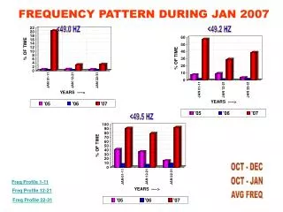
FREQUENCY CONTROL DURING BLACK START OPERATIONS
690 likes | 1.17k Views
FREQUENCY CONTROL DURING BLACK START OPERATIONS. The Isochronous Governor Control Generator and QSE Remote Constant Frequency Control. Sydney Niemeyer: NRG Energy. Introduction.

FREQUENCY CONTROL DURING BLACK START OPERATIONS
E N D
Presentation Transcript
FREQUENCY CONTROL DURING BLACK START OPERATIONS The Isochronous Governor Control Generator and QSE Remote Constant Frequency Control Sydney Niemeyer: NRG Energy
Introduction Frequency Control During Black Start Operations is intended to provide basic dos and don’ts of frequency control during system recovery following a Black out. Review of Isochronous Governor Control of a Resource and Constant Frequency Control of an Island is included.
Objectives At the completion of this course of instruction you will: • Identify the importance of understanding the amount of Primary Frequency Control available during Black Start and Island grid operations. • Identify the amount of Primary Frequency Control available on an Island grid.
Objectives Continued: • Identify the effects of cold load pick-up • Identify the importance of one Isochronous Governor Control Resource per island. • Identify the importance of having one QSE on Constant Frequency Control per island.
Definitions • Area Control Error (ACE): The instantaneous difference between a Balancing Authority’s net actual and scheduled interchange, taking into account the effects of Frequency Bias, correction for meter error, and Automatic Time Error Correction (ATEC), if operating in the ATEC mode. ATEC is only applicable to Balancing Authorities in the Western Interconnection.
Definitions • Area Control Error (ACE): Continued. • Since ERCOT is not synchronously connected to any other Balancing Authority the net actual and scheduled interchange values are always zero. • ERCOT does not correct for meter error in the measurement of actual interchange. • ERCOT does not utilize ATEC. • QSE’s on Constant Frequency Control (Flat Frequency Control) implement the ACE calculation exactly as ERCOT.
Definitions • Automatic Generation Control (AGC): Equipment that automatically adjusts generation in a Balancing Authority Area from a central location to maintain the Balancing Authority’s interchange schedule plus Frequency Bias. AGC may also accommodate automatic inadvertent payback and time error correction.
Definitions • Black Start Resource – A generating unit(s) and its associated set of equipment which has the ability to be started without support from the System or is designed to remain energized without connection to the remainder of the System, with the ability to energize a bus, meeting the Transmission Operator’s restoration plan needs for real and reactive power capability, frequency and voltage control, and that has been included in the Transmission Operator’s restoration plan.
Definitions • Frequency Bias: A value, usually expressed in megawatts per 0.1 Hertz (MW/0.1 Hz), associated with a Balancing Authority Area that approximates the Balancing Authority Area’s response to Interconnection frequency error. • Frequency Bias Setting: A value, usually expressed in MW/0.1 Hz, set into a Balancing Authority ACE algorithm that allows the Balancing Authority to contribute its frequency response to the Interconnection.
Definitions • Frequency Bias Setting: (approved by NERC, not approved by FERC) A number, either fixed or variable, usually expressed in MW/0.1 Hz, included in a Balancing Authority’s Area Control Error equation to account for the Balancing Authority’s inverse Frequency Response contribution to the Interconnection, and discourage response withdrawal through secondary control systems.
Definitions • Droop governor: a governor that changes the electricity generated proportionally to the change in electrical frequency. The slope of this change represents the ratio of electricity generated change to the frequency change. • 100% electricity change for a 5% change in frequency is 5% droop.
Definitions • Isochronous governor: 1) a governor that maintains the same speed in the mechanism controlled regardless of the load. 2) The frequency of the electricity generated is “Flat” or constant and there is zero generator droop. • RTU – Remote Terminal Unit
Content • The Black Start Generator and Frequency Control • The next Start Generator and Frequency Control • Sources of Primary Frequency Control • Sources of Load Dampening • Island Frequency Control
Black Start Resource • Must operate with Isochronous governor in service. • As electrical load is connected to the Black Start resource the governor responds to control the prime mover to maintain frequency to the frequency reference of the governor, 60 Hz.
Isochronous Governor Controller Turbine actual speed = 3600 rpm 2 pole generator = 60.00 Hz Comparator Device Increase Prime Mover if frequency is low, Decrease Prime Mover if frequency is high. Reference input equal to 60.00 Hz
Isochronous Generator Controls to Target Frequency 60 • Load must remain within generator’s capability. • The Isochronous Governor Controller does the rest. 57 63 Generator Frequency Hz
The “Grid” Black Start Black Start
Next Start Black Start Busses cleared except for Black Start plant. Next Start Black Start
Next Start Black Start Next Start Second Black Start unit running. Two islands. Black Start
Next Start Black Start Preparing to Start the Next Start units. Next Start Black Start
Next Start Black Start Next Start units on in the two islands. Next Start Black Start
Island 2 10 MW 20 MW Capacity 8 MW Output 300 MW Capacity 90 MW Output Island 1 Black Start 1 Next Start D 10 MW 15 MW House Load Next Start 2 400 MW Capacity 12 MW Output 5 MW Black Start A 60 MW Capacity 30 MW Output Island 1: 420 MW Capacity 20 MW Load Island 2: 360 MW Capacity 120 MW Load 100 MW
Island 1 • Next Start 2 generator is operating near minimum load. • Unit is typically less stable. • Risk of over-heating steam turbine from too little steam flow. • Minimum flow is 2% to 5% of nameplate depending on manufacturer. • Increase Island load if possible.
Island 2 • Should start next generator to balance load on generators. Increases reserves. • Consider minimum operating conditions on each generator added to the island. • Operating above minimum load on generator provides ability to place controls in AUTO at plant. • Improves Primary Frequency Response delivery.
Island 2 10 MW Island 1 20 MW Capacity 8 MW Output 300 MW Capacity 70 MW Output Black Start 1 Next Start D 10 MW 400 MW Capacity 70 MW Output 15 MW House Load Next Start 2 400 MW Capacity 12 MW Output Island 2: Now with 3 generators on line. Prepare for Constant Frequency Control. 15 MW Black Start A 60 MW Capacity 30 MW Output Island 1: 420 MW Capacity 20 MW Load Island 2: 760 MW Capacity 170 MW Load 100 MW 40 MW
Island Remote Constant Frequency Control • QSE should have MW telemetry from each generator connected. • QSE must have frequency telemetry from the island. • At least one generator must be capable of remote dispatch (AGC). • Black Start generator must be switched to “droop” governor control from isochronous control.
Preparation for Constant Frequency Mode • QSE of the Island generators will not be following ERCOT Base Points. • QSE will calculate Base Points for each controllable generator. • QSE will calculate Island Area Control Error (ACE) using Constant Frequency (Flat Frequency) mode. • Verify that Scheduled Frequency is set to 60.00 Hz.
Determine Island Frequency Response • To calculate ACE of the island, the Frequency Response of the island must be estimated. • ACE = (HzActual – HzScheduled ) * -10 * Bias • Where Bias is the estimated Frequency Response of the island, a negative number. • Determine MW capacity of all generators connected to the island that have a working “droop” governor.
Determine Island Bias • Sum the island MW generation capacity. • Divide the capacity by 30. • The result is the estimated frequency response of the island in –MW/0.1 Hz. • Capacity of frequency responsive generators = 760 MW. • 760 MW/30 = 25.3 MW/0.1 Hz. • Bias setting should be -25 MW/0.1 Hz.
Bias Setting and Load Dampening • Synchronously connected loads provide some frequency response to the island. • Synchronous AC motors on fans, pumps etc. • Florescent lighting. • Under normal conditions on the ERCOT grid, the frequency response of load on the grid can be estimated by multiplying the load (MW) by 0.00245 to get its MW/0.1 Hz contribution.
Bias Setting and Load Dampening Continued • For a 30,000 MW load the frequency response provided by load dampening would be 30,000 * 0.00245 = 73.5 MW/0.1 Hz. • During very cold weather with ERCOT load above 42,000 MW, the multiplier will reduce to 0.0015 since resistive heating load is not frequency responsive. • During early stages of building an island, the load dampening contribution will be very small and can be ignored.
Know Your Generator Control System • Some QSE Generator Control Systems require the Bias value to be entered as a positive number. It is converted to a negative value within the ACE calculation. • It is simple to determine if you have Bias set correctly. • If frequency is below target, the ACE value should cause generation to increase output. • If frequency is above target, the ACE value should cause generator to decrease output.
Bias Setting Lower Better • Initially set Bias lower than calculated until several load pickups have been observed. • Cold Load Pickup will initially appear as 10 times the load increase but will decrease with time. It is better to under control (raise generation slowly) to avoid frequency oscillations as the cold load pickup will decay with time and aid frequency recovery to normal.
Cold Load Pick-up • When adding load remember that cold load pickup is 10 times the steady state load and takes up to 30 minutes to decay. • 1 MW pick up looks like 10 MW and will cause frequency to drop to 59.96 from 60 Hz with an island Bias of 25 MW/0.1 Hz. • 3 MW pick up looks like 30 MW and will cause frequency to drop to 59.88 Hz.
Frequency Control in Constant Frequency Mode • Will NOT be similar to having the Black Start Generator on Isochronous control. • Frequency movement will be much greater. • Frequency recovery to schedule will be dependent on the ramp rate of the generator(s) on AGC. • Sustained Primary Frequency Response from all generators connected is critical for stable frequency control.
Keep Operating Margin • The QSE should closely monitor operating margins on all the AGC generators. • If Up or Down margin gets low, manually adjust non-AGC generators to give AGC generators more room to operate. • When moving other generation, consider the ramp rate of the AGC generators to avoid excessive ramping demands.
Prepare for Tying Islands Together • Synchronize smaller island to the larger island. (Smaller in MW load.) • Before synchronization, determine MW capacity of incoming island that will not be on Constant Frequency Control. • Calculate new Bias Setting of combined area by adding capacity of frequency responsive generators to existing island.
Bias Setting For Two Islands Connected • Existing Island on Constant Frequency Mode capacity: 1260 MW. • Incoming Island on Isochronous governor control by the Black Start generator. Capacity 420 MW. • Combined capacity: 1680 MW. • Bias Setting: 1680/30 = -56 MW/0.1 Hz. • Be sure to include only generation capacity that is frequency responsive.
10 MW 20 MW Capacity 8 MW Output 300 MW Capacity 70 MW Output Island 1 Black Start 1 Next Start D Sync Point 10 MW 400 MW Capacity 70 MW Output 15 MW House Load Next Start 2 500 MW Capacity 90 MW Output 400 MW Capacity 12 MW Output Island 2 15 MW Preparing to synchronize Island 1 to Island 2. Black Start A 60 MW Capacity 30 MW Output Island 1: 420 MW Capacity 20 MW Load Island 2: 1260 MW Capacity 260 MW Load 100 MW 130 MW
Synchronizing Two Islands • In the smaller island, take the Isochronous Black Start generator out of Isochronous governor control and place it in droop mode. • At Sync point, observe island voltages and match appropriately. • Observe Sync scope and adjust generation in smaller island to achieve a slightly “fast” rotation of the scope. Close the breaker at the proper phase alignment.
Connecting Two Islands When Both are on Constant Frequency • The process is the same as the isochronous generator. • Take the smaller MW load island (incoming generation) off Constant Frequency mode. • Field operator at Sync location should have contact with QSE of the incoming island to direct generation up or down to achieve proper synchronization. • Only one QSE remains on Constant Frequency mode after synchronization.
10 MW 20 MW Capacity 8 MW Output 300 MW Capacity 70 MW Output 1 Island Black Start 1 Next Start D Sync Point 10 MW 400 MW Capacity 70 MW Output 15 MW House Load Next Start 2 500 MW Capacity 90 MW Output 400 MW Capacity 12 MW Output 15 MW Synchronized Black Start A 60 MW Capacity 30 MW Output Island: 1680 MW Capacity 280 MW Load Bias Setting: -56 MW/0.1 Hz 100 MW 130 MW
After Connecting Islands • QSE that remains on Constant Frequency mode adjusts Bias Setting to account for the additional frequency responsive generation. • Communicates through ERCOT for adjustments in generation operated by the other QSE. • Close additional tie lines to strengthen island connections.
10 MW 20 MW Capacity 8 MW Output 300 MW Capacity 70 MW Output 1 Island Black Start 1 Next Start D 10 MW 400 MW Capacity 70 MW Output 15 MW House Load Next Start 2 500 MW Capacity 90 MW Output 400 MW Capacity 12 MW Output 15 MW Synchronized Black Start A 60 MW Capacity 30 MW Output Island: 1680 MW Capacity 280 MW Load Bias Setting: -56 MW/0.1 Hz 100 MW 130 MW
One Generator on Isochronous Governor Control per Island or One QSE on Constant Frequency Control per Island Only one boss
Two Isochronous Governor Controls Active on One Island • Each generator will control to a slightly different frequency. • The generator controlling to the higher frequency will increase output. • The generator controlling to the lower frequency will decrease output.
Isochronous Governor Controller Small conversion errors can exist at several locations. 1. Resolution of actual frequency, turbine speed. Turbine actual speed = 3600 rpm 2 pole generator = 60.00 Hz Comparator Device Increase Prime Mover if frequency low, Decrease Prime Mover if frequency high. 3. Resolution of the comparator circuitry/logic. Reference input equal to 60.00 Hz 2. Resolution of reference frequency, is it an analog signal or digital.
Gen A operating at 20 MW output and on Isochronous Control. Controlling to 60.008 Hz Gen B switched to Isochronous Control and controlling to 60.002 Hz. Gen B operating at 15 MW output and on Droop Control.
Why Only One QSE on Constant Frequency Mode • Just like having two Isochronous governor control generators active on the same island, Constant Frequency mode will generally result in undesired actions. • The problem is that neither control system will measure the exact same value for the frequency. • Neither control system will measure the exact same value for the frequency reference.
QSE Constant Frequency Mode QSE A on Constant Frequency Control Island ACE = (HzActual – 60.00) * -10 * Bias Island Frequency Bias ACE RTU RTU Target Frequency 60.00 Hz Gen 2 MW and/or AGC Telemetry Gen 1 MW, Hz & AGC Telemetry