Download
1 / 18
180 likes | 305 Views
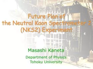
Future Plan of the Neutral Kaon Spectrometer 2 (NKS2) Experiment. Masashi Kaneta Department of Physics Tohoku University. Upgrade Project. Physics motivation K + Y coincidence measurement Advantage No Fermi motion correction Reaction Plane will be defined Direct comparison with Model

E N D
Future Plan ofthe Neutral Kaon Spectrometer 2(NKS2) Experiment Masashi Kaneta Department of Physics Tohoku University
Upgrade Project • Physics motivation • K+Y coincidence measurement • Advantage • No Fermi motion correction • Reaction Plane will be defined • Direct comparison with Model • Lambda polarization • Detector upgrade • Replacing inner detector • Replace straw drift chamber by a 3D tracker • increase the acceptance • Two-side-read-out hodoscope • increase dE/dx and TOF resolution • better particle separation Masashi Kaneta, Tohoku Univ.
NKS2 detectors • Two Drift Chambers • Cylindrical Drift Chamber (CDC) and Straw Drift Chamber (SDC) • Two Hodoscope • Inner and Outer Hodoscope (IH and OH) • Electron Veto 110 mm • New inner detectors should be fit in 630H x f110-400 tube 630 mm EV OH CDC IH SDC 400 mm Masashi Kaneta, Tohoku Univ.
Current/Future Inner Detectors Position 42.6º VDC SDC IH 380 IH 65 78 160 134 100 300 Liquid Deuterium target holder region 766 OH 712 286 232 CDC 17.3º 530 748 630 55 200 210 1200 800 Masashi Kaneta, Tohoku Univ.
Vertex Drift Chamber Design vv’ vv’ uu’ uu’ • Requirements • As possible as small cell • but limited by feedthrough (f3mm) • At least 6 layers with stereo wires • Decision • Trapezoid (almost square) cell shape • Half cell size: 4 mm • 8 layers • uu’ vv’ uu’ vv’ • increasing stereo angle with radius:6.0 - 11.1° • Drift gas = Ar:Ethane(50:50) 65 mm 55 mm 137 mm Masashi Kaneta, Tohoku Univ.
Frame Safety factor min: 6.2 • Concept • Less material • but to be strong • ~216 kg total wire tension • CFRP pillar • 20Lx40Wx0.5TH mm3 • 1.0TH = 0.004 X0 • target chamber: 0.009 X0 IH: 0.012 X0 • End-cap f160 mm 426 mm height of pillar • 390 mm wire height • This design has the most large safety factor in plans Masashi Kaneta, Tohoku Univ.
Readout 43.7 94.5 100 63.6 21.9 30° 43.7 16.3 side view bottom view • FEE • ASD • Sony ASD chip • GNA-220 • Align on VDC • like windmill • TDC • VME multi-hit TDC • Atlas muon TDC chip • Amsk co. • same with CDC Masashi Kaneta, Tohoku Univ.
Acceptance for K0S or L Generated distribution: SLA model • The acceptance with new chamber • ~3 times for K0S • ~1.5 times for • Note: these values vary about 10%, depend on models used for input L (p p-channel) K0S (p+ p- channel) (1): all events (2): the two daughters pass through VDC with two OH his (3): two daughters pass through OH Note: Decay volume cut is applied for (2) and (3) and lost ~80% of events Masashi Kaneta, Tohoku Univ.
Acceptance for K0S + L Events • The acceptance will increase • ~8 times L (p p-channel) K0S (p+ p- channel) (1): all events (2): the four daughters pass through VDC with two OH Hits (3): four daughters pass through OH Note: No decay volume cut is applied Masashi Kaneta, Tohoku Univ.
Polarization Measurement t q pp LCM pp Transverse polarization measurement • Acceptance correction • May vary with • Cos(qKcm), Eg • momentum • Polarization • Test results • No Polarization dependences • PL is smeared by resolution • factor ~0.9 pL t = pg×pL reaction plane in CM polarization Acceptance decay parameter 0.642 (PDG) pN qK pg pK Masashi Kaneta, Tohoku Univ.
Model Predictions: Self L Polarization g+n K0+L g+p K++L SLA (rKK=-2.087) KaonMAID L Polarization SA1 (P. Bydzolvski) q of Kaon in CM [degree] Masashi Kaneta, Tohoku Univ.
Schedule March April May June July • The test experiment of new detectors will be before summer shutdown construction VDC check at test bench Installation in NKS2 Test Exp. w/ Beam IH design construction Masashi Kaneta, Tohoku Univ.
Summary • The detector upgrade project is on going • Goal: K+Y coincidence measurement • Increasing acceptance of tracking • Increasing start time resolution of TOF • better /K/p separation toward K++Y measurement • New inner detectors • Expecting ~8 times K0S+L events • Schedule • Test experiment before summer • Beam time will be requested Masashi Kaneta, Tohoku Univ.
Materials • CFRP • C:H:O = 75:5:20 • density = 1.55 g/cm3 • radiation length = 26.66 cm • 1 mm thickness = 0.0038 X0 • Scintillator • C:H = 8:8 atoms • density = 1.032 g/cm3 • radiation length = 42.43 cm • 5 mm thickness = 0.0118 X0 • Target cell • 0.009X0 Masashi Kaneta, Tohoku Univ.