Download

1 / 13
130 likes | 221 Views
Electromagnetic Induction. AC Circuits and transformers. Effective Current. Emf in ac circuits is equivalent to potential difference in dc circuits Resistance, current, and emf can all be measured using a multimeter

E N D
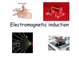
Electromagnetic Induction AC Circuits and transformers
Effective Current • Emf in ac circuits is equivalent to potential difference in dc circuits • Resistance, current, and emf can all be measured using a multimeter • Induced emf as a function of time = maximum emf * sine of the angular frequency of rotation * time • Δv = Δvmax * sinω * t • Instantaneous current = maximum current * sine of the angular frequency of rotation * time • i = Imax* sinω * t
Effective Current • Since alternating current is constantly reversing, maximum current and emf values are not as useful as they are in direct current • Of more importance are instantaneous and root-mean-square (rms) values • Rms current – the amount of direct current that dissipates as much energy in a resistor as an instantaneous alternating current does during a complete cycle • - the value of alternating current that gives the same heating effect that the corresponding value of direct current does • An equivalent value allowing for accurate comparisons between alternating and direct current • Power can be calculated by using the appropriate rms values in the equations given previously
Effective Current • Power = rms current squared * resistance • Power = one-half * maximum current squared * resistance • P = (Irms)2R = ½(Imax)2R • Ohm’s law still applies in ac circuits • Rms potential difference = rms current * resistance • Vrms = Irms*R
Effective Current • Sample problem: A generator with a maximum output emf of 205V is connected to a 115 resistor. Calculate the rms potential difference. Find the rms current through the resistor. Find the maximum ac current in the circuit. • Vmax = 205V R = 115 • Vrms = ? Irms = ? Imax = ? • Vrms = .707*Vmax • Irms= Vrms / R • Irms = .707*Imax
Effective Current • Resistance influences current in an ac circuit • The ac potential difference (ac voltage) measured in an electrical outlet is a rmsemf with a value of 120V • Maximum emf value for an outlet is about 170V • Ammeters and voltmeters (and therefore multimeters) that measure alternating current are calibrated to measure rms values for current and emf (voltage)
Transformers • Transformer – a device that increases or decreases the emf of alternating current • In its simplest form, a transformer consists of two coils of wire wrapped around an iron core • The first coil, or primary or input coil, is connected to a voltage source • The second coil, or secondary or output coil, is connected to a resistor or other load • The relative number of times the coils are wrapped around the iron core determines what happens to the voltage • If the primary coil has more loops, the voltage decreases • Step-down transformer • If the secondary coil has more loops, the voltage increases • Step-up transformer
Transformers • Transformer Equation • Induced emf in secondary coil = (number of turns in secondary coil) / (number of turns in primary coil) * applied emf in primary coil • ΔV2 =N2 / N1 * ΔV1 • Can’t have something for nothing • Due to energy loss due to heating and radiation, so the output power will be less than the input power • Any increase in voltage must be offset by a proportional decrease in current • Real transformers have efficiency values of 90-99% • To minimize power lost by resistive heating (I2R loss) in transmission lines, electric lines have high emf values and low currents • Main lines have emf = 230000V • Regional lines have emf = 20000V • Customer lines have emf = 120V
Transformers • Transformers
Transformers • The ignition coil in a gasoline engine is a transformer • Changes 12 dc V into an emf of 100000V to ignite and burn fuel when sparkplug fires • Crank angle sensor detects the crankshafts position to determine when the engine cylinder’s contents are at maximum compression