Download
1 / 17
180 likes | 878 Views
Line differential relay 7SD52. Line differential relay for HV and UHV lines/cables with a serial communication interface 7SD52. Protection and communication join together Three benefits of the 7SD52.

E N D
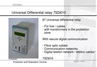
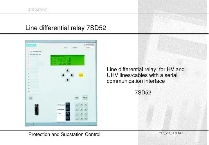
Line differential relay 7SD52 Line differential relay for HV and UHV lines/cables with a serial communication interface 7SD52
Protection and communication join togetherThree benefits of the 7SD52 • Differential protection for the universal use with easy to handle settingsTwo up to six line ends , for serial and parallel compensated lines, handles transformers and compensation coils within the protection zone,tripping time approx. 15 ms with fast high set element • Additional functions for very long overhead lines and cablesConsidation of local CT errors, charge current compensation (step 2), increased setpoint during switching-on conditions • Direct and modular connection to fibre optic and digital communication networks
PCM multi- plexer PCM multi-plexer e o Application for a three terminal configuration Monomode fibre optic cable up to 35 km with 1300 nm interface Monomode fibre optic cable up to 10 km (1300 nm modul) Distance relay 7SA52 X21 G703.1 SDH comms-network e o 820 nm max. 3 km o e Option:I-REGB Comms- converter G703.1: 64 kBitX21: N*64 kBit (1N8) time synchronisation
O O E O Scope of functions / Hardware options Options for the Protection Interface Scope of functions - Fast high set element with charge comparision- Sensitive normal trip stage with vector summation principle - Autoreclosure 1/3 pole - Communication features - Commissioning aid - Overload protection - Backup-/emergency overcurrent - Multiterminal extention- Switch on to fault protection- 4 remote commands 24 remote signals Relay Hardware 820 nm1,5 / 3 km multimode ST- connector 3Iph, and IE 4 U 8 binary inputs 16 contacts 1 - 2 protection interfaces System interface PC-interface Time synchronisation internal 1300 nm10 kmmonomode ST- connector internal ½*19´´ 16 binary inputs 24 contacts 24 binary inputs 32 contacts Option: 5 fast trip contacts O 1300 nm35 kmmonomode FC- connector internal ElectricalX21 G703.1interface 820 nm1,5 kmST-connectors 1*19´´ External converter
Protection interface 2Port E Synchronous N x 64kB/sec 7SD52 DIGSI 4; also for modem connectionand Browser service-interface Interfacemodul 1 RS485 or FO or RS232 DIGSI local Browser local-PC interface GPS-receiver Serial time sync. input Hardware option of the comms interfaces Remote line end 2 Plug in modules Remote line end 1 Protection interface 1Port D Synchronous N x 64kB/sec Subst. control interface Substation control communication modules Interfacemodul 2 FO (Fibre optic) or RS485or RS232 Available ProtocolsIEC - standard RS485 or FO
Main board of the relay with it´s Communication - Interfaces Main processor board of the relay Sockets for the communicationmodules
Main protection functionFeatures of the differential function • Phase selective multiend differential protection(2 - 6 ends). Tripping time 15 ms with fast charge comparison protection. • Fundamental vector comparison for the sensitive trip stage. • Dynamic increase of differential setpoint during switch-on of long lines / cables (settable time) • CT saturation detector (only 5 ms saturation free time due to external faults necessary) • Phase selective intertrip within 15 ms • Settable delay time for single phasefaults (feature for inductive compensated networks) • Option: Inrush 2nd harmonic restraint with vector group adaption. Undelayed trip for high fault currents • Optional Lockout function
Adaptive differential relayingConsideration of CT- errors and comms-errors I1 I2 IDiffIN Tripping area I2 I3 I3 Restraint area I1 IDiff> I1 I IN Phasor summation: Error summation: IDiff = I1 + I2 + I3 I = IDiff> + Linear CT-error ( + Syncronization error IK) Trip, if diff.current exceeds the max. permissible error
To complete the 7SD52Additional functions • 3 stage backup- or emergency O/C protection(Can be activated automatically if the communication with the remote end is >50 ms interrupted) • Overload function (Thermal replica with IOperation) • User definable logic and control functions(AND, OR, NOT, Timer, Flip-Flop) • 4 remote commands via binary input or logic inputs (destination is adressable), 24 remote signals • Operational values: currents, voltages, power,delay time, differential current - remote end refresh 2 s • Fault recorder with voltages, currents, binary traces and differential and restraint current per phase • Fast monitoring functions(Fast broken wire supervision, Current symmetry) • Switch On to Fault protection • Option: Three pole and single pole AR (Single pole AR during 2pole fault without earth possible, adaptive AR)
Familiar with digital communication networks Features of the relay to relay communication • Synchronous data transmission by HDLC- protocol • Permanent supervision of the data transmission • Measurement and compensation of signal transmission time(max. 20 ms) • Counts number of invalid telegramsBlocking the diff.protection if transmission failure rate is too high • Settings for the data transmission (N*64 kBit/s, N settable from 1 - 8, synchronous HDLC-protocol) • Communication device addresses(Protection devices are clearly assigned to a defined protection section) • Detection of reflected data in the loops in comms- network • Step 2: Microsecond exact time synchronisation via satellite (civil - IRIG-B)(If signal transmission time depends on the transmission direction, Online high resolution fault recorder)
side 2 I2 side 3 I3 I1 side 1 Ring and Chain topologie Automatic change fromclosed ring to chain, if one connection is lost or not available side 2 side 3 I2 Connection to other diff. relays I3 I3+I1 I2 I1+I2 I3 I1 I3+I1 I1+I2 side 1 Closed ring Partial current summation
Topologies: Chain topology for max. 6 line ends 1 2 3 PI1 PI1 PI2 PI1 PI2 PI - Protection Interface PI1 6 5 4 PI1 PI2 PI1 PI2
Topologies: Ring topology, 6 line ends 1 2 3 PI2 PI1 PI2 PI1 PI1 PI2 PI2 PI1 6 5 4 PI1 PI2 PI1 PI2 PI - Protection Interface
Plug and Protect Commissiong helps and test features • Signal transmission timeMean value of transmit and receive direction • Generation of signals for switching test loopsSending of defined telegram patterns looped back to the receive input of the transmitting relay • Absolute value and phase measurement of currentsLocal measurement of angle between IL1, IL2, IL3,Angle between currents of each phase from remote • CB test trip • Counting of faulty telegrams in % per minute and hour • Activation of binary inputs and outputs by operating software DIGSI 4. • Display of the status of binary inputs • Test telegrams to the substation control system • Automatic Switchover from 3 line to 2 line end configuration (while commissioning 3rd line end) • Complete commissioning support with DIGSI 4 andbrowser based PC-software IL1_2 Phi1->2 IL1_1 IL2_1 IL2_2 IL3_2 IL3_1