Download
1 / 71
710 likes | 863 Views
The LHCb Way of Computing The approach to its organisation and development. John Harvey CERN/ LHCb DESY Seminar Jan 15 th , 2001. Talk Outline. Brief introduction to the LHCb experiment Requirements on data rates and cpu capacities Scope and organisation of the LHCb Computing Project

E N D
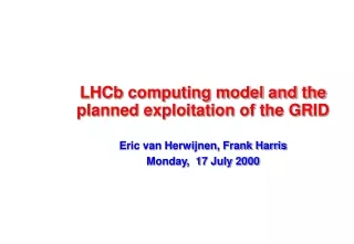
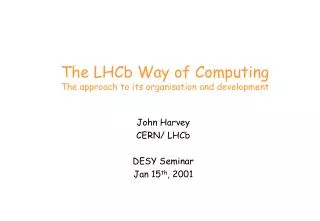
The LHCb Way of Computing The approach to its organisation and development John Harvey CERN/ LHCb DESY Seminar Jan 15th, 2001
Talk Outline • Brief introduction to the LHCb experiment • Requirements on data rates and cpu capacities • Scope and organisation of the LHCb Computing Project • Importance of reuse and a unified approach • Data processing software • Importance of architecture-driven development and software frameworks • DAQ system • Simplicity and maintainability of the architecture • Importance of industrial solutions • Experimental Control System • Unified approach to controls • Use of commercial software • Summary
The LHCb Experiment • Special purpose experiment to measure precisely CP asymmetries and rare decays in B-meson systems • Operating at the most intensive source of Bu, Bd, Bs and Bc,i.e. the LHC at CERN • LHCb plans to run with an average luminosity of 2x1032cm-2s-1 • Events dominated by single pp interactions - easy to analyse • Detector occupancy is low • Radiation damage is reduced • High performance trigger based on • High pTleptons andhadrons (Level 0) • Detached decay vertices (Level 1) • Excellent particle identification for charged particles • K/p: ~1GeV/c < p < 100GeV/c
The LHCb Detector • At high energies b- and b-hadrons are produced in same forward cone • Detector is a single-arm spectrometer with one dipole • min = ~15 mrad (beam pipe and radiation) • max = ~300 mrad (cost optimisation) Polar angles of b and b-hadrons calculated using PYTHIA
Brazil Ukraine Finland France UK Switzerland Germany Italy Poland PRC Netherlands Romania Russia Spain The LHCb Collaboration 49 institutes 513 members
LHCb in numbers • Expected rate from inelastic p-p collisions is ~15 MHz • Total b-hadron production rate is ~75 kHz • Branching ratios of interesting channels range between 10-5-10-4 giving interesting physics rate of ~5 Hz
Timescales • LHCb experiment approved in September 1998 • Construction of each component scheduled to start after approval of corresponding Technical Design Report (TDR) : • Magnet, Calorimeter and RICH TDRs submitted in 2000 • Trigger and DAQ TDRs expected January 2002 • Computing TDR expected December 2002 • Expect nominal luminosity (2x1032 cm-2sec –1) soon after LHC turn-on • Exploit physics potential from day 1 • Smooth operation of the whole data acquisition and data processing chain will be needed very quickly after turn–on • Locally tuneable luminosity long physics programme • Cope with long life-cycle of ~ 15 years
Requirements and Resources • More stringent requirements … • Enormous number of items to control - scalability • Inaccessibility of detector and electronics during datataking -reliability • intense use of software in triggering (Levels 1, 2, 3) - quality • many orders of magnitude more data and CPU - performance • Experienced manpower very scarce • Staffing levels falling • Technology evolving very quickly (hardware and software) • Rely very heavily on very few experts (1 or 2) - bootstrap approach • The problem - a more rigorous approach is needed but this is more manpower intensive and must be undertaken under conditions of dwindling resources
Importance of Reuse • Put extra effort into building high quality components • Become more efficient by extracting more use out of these components (reuse) • Many obstacles to overcome • too broad functionality / lack of flexibility in components • proper roles and responsibilities not defined ( e.g. architect ) • organisational - reuse requires a broad overview to ensure unified approach • we tend to split into separate domains each independently managed • cultural • don’t trust others to deliver what we need • fear of dependency on others • fail to share information with others • developers fear loss of creativity • Reuse is a management activity - need to provide the right organisation to make it happen
Detector Control System Detector Description Detector Description Detector Description Simulation DAQ Software Analysis Event Display Offline System Event Display Online System Message System Traditional Project Organisation DAQ Hardware Message System
A Process for reuse Manage Plan, initiate, track, coordinate Set priorities and schedules, resolve conflicts Build Develop architectural models Choose integration standards Engineer reusable components Support Support development Manage & maintain components Validate, classify, distribute Document, give feedback Assemble Design application Find and specialise components Develop missing components Integrate components Requirements (Existing software and hardware) Systems
Operations M Software Development Support Code Mgt, Release Mgt, Tools, Training Documentation Web M Distributed Computing Facilities CPU Farms Data storage Computing Model Production Tools GRID M Reconstruction M Simulation Experiment Control System Detector controls Safety System Run Control system DAQ System Timing Fast Control, Readout Unit Event Builder Event Filter Farm M M M Analysis M Trigger M GAUDI Framework Architecture Spec. Det Desc, Visualisation GEANT4, XML,… Controls Framework Architecture Spec, SCADA, OPC, … DAQ Framework Architecture Spec, Simulation Model, TTC, NP, NIC,.. A C Computing Coordinator RC Regional Centre Rep M Project Manager A Software Architect E Project Engineer LHCb ComputingProject Organisation National Computing Board Computing Steering Group Technical Review RC M E RC C M C A E M A RC Manage Assemble Build Support
Software architecture • Definition of [software] architecture [1] • Set or significant decisions about the organization of the software system • Selection of the structural elements and their interfaces which compose the system • Their behavior -- collaboration among the structural elements • Composition of these structural and behavioral elements into progressively larger subsystems • The architectural style that guides this organization • The architecture is the blue-print (architecture description document) [1] I. Jacobson, et al. “The Unified Software development Process”, Addison Wesley 1999
Software Framework • Definition of [software] framework [2,3] • A kind of micro-architecture that codifies a particular domain • Provides the suitable knobs, slots and tabs that permit clients to customise it for specific applications within a given range of behaviour • A framework realizes an architecture • A large O-O system is constructed from several cooperating frameworks • The framework is real code • The framework should be easy to use and should provide a lot of functionality [2] G. Booch, “Object Solutions”, Addison-Wesley 1996 [3] E. Gamma, et al., “Design Patterns”, Addison-Wesley 1995
Benefits • Having an architecture and a framework: • Common vocabulary, better specifications of what needs to be done, better understanding of the system. • Low coupling between concurrent developments. Smooth integration. Organization of the development. • Robustness, resilient to change (change-tolerant). • Fostering code re-use architecture framework applications
What’s the scope? • Each LHC experiment needs a framework to be used in their event data processing applications • physics/detector simulation • high level triggers • reconstruction • analysis • event display • data quality monitoring,… • The experiment framework will incorporate other frameworks: persistency, detector description, event simulation, visualization, GUI, etc.
Software Structure Applications built on top of frameworks and implementing the required physics algorithms. High level triggers Reconstruction Simulation Analysis One main framework Various specialized frameworks: visualization, persistency, interactivity, simulation, etc. Frameworks Toolkits A series of basic libraries widely used: STL, CLHEP, etc. Foundation Libraries
GAUDI Object Diagram Converter Converter Application Manager Converter Event Selector Transient Event Store Data Files Message Service Persistency Service Event Data Service JobOptions Service Algorithm Algorithm Algorithm Data Files Transient Detector Store Particle Prop. Service Persistency Service Detec. Data Service Other Services Data Files Transient Histogram Store Persistency Service Histogram Service
GAUDI Architecture: Design Criteria • Clear separation between data and algorithms • Three basic types of data: event, detector, statistics • Clear separation between persistent and transient data • Computation-centric architectural style • User code encapsulated in few specific places: algorithms and converters • All components with well defined interfaces and as generic as possible
Status • Sept 98 – project started GAUDI team assembled • Nov 25 ’98 - 1- day architecture review • goals, architecture design document, URD, scenarios • chair, recorder, architect, external reviewers • Feb 8 ’99 - GAUDI first release (v1) • first software week with presentations and tutorial sessions • plan for second release • expand GAUDI team to cover new domains (e.g. analysis toolkits, visualisation) • Nov ’00 – GAUDI v6 • Nov 00 – BRUNEL v1 • New reconstruction program based on GAUDI • Supports C++ algorithms (tracking) and wrapped FORTRAN • FORTRAN gradually being replaced
Collaboration with ATLAS • Now ATLAS also contributing to the development of GAUDI • Open-Source style, expt independent web and release area, • Other experiments are also using GAUDI • HARP, GLAST, OPERA • Since we can not provide all the functionality ourselves, we rely on contributions from others • Examples: Scripting interface, data dictionaries, interactive analysis, etc. • Encouragement to put more quality into the product • Better testing in different environments (platforms, domains,..) • Shared long-term maintenance • Gaudi developers mailing list • tilde-majordom.home.cern.ch/~majordom/news/gaudi-developers/index.html
LHC-B Detector Data rates VDET TRACK ECAL HCAL MUON RICH 40 MHz Level 0 Trigger 40 TB/s Level-0 Front-End Electronics Level-1 1 MHz Timing & Fast Control L0 Fixed latency 4.0 ms 1 TB/s 40 kHz L1 Level 1 Trigger LAN 1 MHz Front-End Multiplexers (FEM) Front End Links 6 GB/s Variable latency <1 ms RU RU RU Read-out units (RU) Throttle Read-out Network (RN) 6 GB/s SFC SFC Sub-Farm Controllers (SFC) Variable latency L2 ~10 ms L3 ~200 ms Control & Monitoring Storage 50 MB/s Trigger Level 2 & 3 Event Filter CPU CPU CPU CPU Trigger/DAQ Architecture
60x1GbE 60x1GbE Foundry BigIron 15000 Foundry BigIron 15000 12x10GbE 3 3 3 3 Foundry BigIron 15000 Foundry BigIron 15000 60x1GbE 60x1GbE Event Building Network • Requirements • 6 GB/s sustained bandwidth • Scalable • ~120 inputs (RUs) • ~120 outputs (SFCs) • commercial and affordable (COTS, Commodity?) • Readout Protocol • Pure push-through protocol of complete events to one CPU of the farm • Destination assignment following identical algorithm in all RUs (belonging to one partition) based on event number • Simple hardware and software • No central control perfect scalability • Full flexibility for high-level trigger algorithms • Larger bandwidth needed (+~50%) compared with phased event-building • Avoiding buffer overflows via ‘throttle’ to trigger • Only static load balancing between RUs and SFCs
Readout Unit using Network Processors IBM NP4GS3 • 4 x 1Gb full duplex Ethernet MACs • 16 RISC processors @ 133 MHz • Up-to 64 MB external RAM • Used in routers RU Functions • EB and formatting • 7.5 msec/event • ~200 kHz evt rate
~50 MB/s ~0.5 MB/s Sub Farm Controller (SFC) Alteon Tigon 2 • Dual R4000-class processor running at 88 MHz • Up to 2 MB memory • GigE MAC+link-level interface • PCI interface • ~90 kHz event fragments/s Development environment • GNU C cross compiler with few special features to support the hardware • Source-level remote debugger ‘Standard’ PC PCI Bus Local Bus Readout Network (GbE) Smart NIC CPU PCI Bridge Subfarm Network (GbE) NIC Memory ~50 MB/s ~0.5 MB/s Controls Network (FEth) Control NIC
Control Interface to Electronics • Select a reduced number of solutions to interface Front-end electronics to LHCb’s control system: • No radiation (counting room): Ethernet to credit card PC on modules • Low level radiation (cavern):10Mbits/s custom serial LVDS twisted pairSEU immune antifuse based FPGA interface chip • High level radiation (inside detectors):CCU control system made for CMS trackerRadiation hard, SEU immune, bypass • Provide support (HW and SW) for the integration of the selected solutions
Control and Monitoring LHC-B Detector Data rates VDET TRACK ECAL HCAL MUON RICH 40 MHz Level 0 Trigger 40 TB/s Level-0 Front-End Electronics Level-1 1 MHz Timing & Fast Control L0 Fixed latency 4.0 ms 1 TB/s 40 kHz L1 Level 1 Trigger LAN 1 MHz Front-End Multiplexers (FEM) Front End Links 6 GB/s Variable latency <1 ms RU RU RU Read-out units (RU) Throttle Read-out Network (RN) 6 GB/s SFC SFC Sub-Farm Controllers (SFC) Variable latency L2 ~10 ms L3 ~200 ms Control & Monitoring Storage 50 MB/s Trigger Level 2 & 3 Event Filter CPU CPU CPU CPU
Experimental Control System • The Experiment Control System will be used to control and monitor the operational state of the detector, of the data acquisition and of the experimental infrastructure. • Detector controls • High and Low voltages • Crates • Cooling and ventilation • Gas systems etc. • Alarm generation and handling • DAQ controls • RUN control • Setup and configuration of all readout components (FE, Trigger, DAQ, CPU Farm, Trigger algorithms,...)
System Requirements • Common control services across the experiment • System configuration services – coherent information in database • Distributed information system – control data archival and retrieval • Error reporting and alarm handling • Data presentation – status displays, trending tools etc. • Expert system to assist shift crew • Objectives • Easy to operate – 2/3 shift crew to run complete experiment • Easy to adapt to new conditions and requirements • Implies integration of DCS with the control of DAQ and data quality monitoring
Integrated System – trending charts DAQ Slow Control
Integrated system – error logger ALEPH error logger, ERRORS + MONITOR + ALARM 2-JUN 11:30 ALEP R_ALEP_0 RUNC_DAQ ALEPH>> DAQ Error 2-JUN 11:30 ALEP TPEBAL MISS_SOURCE TPRP13 <1_missing_Source(s)> 2-JUN 11:30 ALEP TS TRIGGERERROR Trigger protocol error(TMO_Wait_No_Busy) 2-JUN 11:30 TPC SLOWCNTR SECTR_VME VME CRATE fault in: SideA Low DAQ Slow Control
Scale of the LHCb Control system • Parameters • Detector Control: O (105) parameters • FE electronics: Few parameters x 106 readout channels • Trigger & DAQ: O(103) DAQ objects x O(102) parameters • Implies a high level description of control components (devices/channels) • Infrastructure • 100-200 Control PCs • Several hundred credit-card PCs. • By itself a sizeable network (ethernet)
LHCb Controls Architecture Conf. DB, Archives,Log files, … Technologies Storage Supervision SCADA Users Servers WAN LAN Process Management . . . OPC LAN Controller/ PLC Communication Other systems (LHC, Safety, ...) VME Fieldbus PLC Field Management Fieldbuses Experimental equipment Devices
Supervisory Control And Data Acquisition • Used virtually everywhere in industry including very large and mission critical applications • Toolkit including: • Development environment • Set of basic SCADA functionality (e.g. HMI, Trending, Alarm Handling, Access Control, Logging/Archiving, Scripting, etc.) • Networking/redundancy management facilities for distributed applications • Flexible & Open Architecture • Multiple communication protocols supported • Support for major Programmable Logic Controllers (PLCs) but not VME • Powerful Application Programming Interface (API) • Open Database Connectivity (ODBC) • OLE for Process Control (OPC )
Benefits/Drawbacks of SCADA • Standard framework => homogeneous system • Support for large distributed systems • Buffering against technology changes, Operating Systems, platforms, etc. • Saving of development effort (50-100 man-years) • Stability and maturity – available immediately • Support and maintenance, including documentation and training • Reduction of work for the end users • Not tailored exactly to the end application • Risk of company going out of business • Company’s development of unwanted features • Have to pay
Commercial SCADA system chosen • Major evaluation effort • technology survey looked at ~150 products • PVSS II chosen from an Austrian company (ETM) • Device oriented, Linux and NT support • The contract foresees: • Unlimited usage by members of all institutes participating in LHC experiments • 10 years maintenance commitment • Training provided by company - to be paid by institutes • Licenses available from CERN from October 2000 • PVSS II will be the basis for the development of the control systems for all four LHC experiments (Joint COntrols Project)
Controls Framework • LHCb aims to distribute with the SCADA system a framework • Reduce to a minimum the work to be performed by the sub-detector teams • Ensure work can be easily integrated despite being performed in multiple locations • Ensure a consistent and homogeneous DCS • Engineering tasks for framework : • Definition of system architecture (distribution of functionality) • Model standard device behaviour • Development of configuration tools • Templates, symbols libraries, e.g. power supply, rack, etc. • Support for system partitioning (uses FSM) • Guidelines on use of colours, fonts, page layout, naming, ... • Guidelines for alarm priority levels, access control levels, etc. • First Prototype released end 2000
Application Architecture ECS LHC DCS DAQ Vertex Tracker Muon Vertex Tracker Muon HV Temp HV GAS HV GAS FE RU FE RU FE RU SAFETY
Summary • Organisation has important consequences for cohesion, maintainability, manpower needed to build system • Architecture driven development maximises common infrastructure and results in systems more resilient to change • Software frameworks maximuse level of reuse and simplify distributed development by many application builders • Use of industrial components (hardware and software) can reduce development effort significantly • DAQ is designed with simplicity and maintainability in mind • Maintain a unified approach – e.g. same basic infrastructure for detector controls and DAQ controls