Download
1 / 52
520 likes | 677 Views
Gamma-ray Large Area Space Telescope. GLAST Large Area Telescope: AntiCoincidence Detector (ACD) Critical Design Review (CDR) January 7 & 8, 2003. Agenda. DAY 1 – January 7 Section 1 - ACD Overview 8:30-9:15 Section 2 - ACD Management 9:15-9:50 BREAK 9:50-10:00

E N D
Gamma-ray Large Area Space Telescope GLAST Large Area Telescope: AntiCoincidence Detector (ACD) Critical Design Review (CDR) January 7 & 8, 2003
Agenda DAY 1 – January 7 Section 1 - ACD Overview 8:30-9:15 Section 2 - ACD Management 9:15-9:50 BREAK 9:50-10:00 Section 3 - Systems Engineering 10:00-11:00 Section 4 – ACD Science 11:00-11:45 LUNCH 11:45-12:45 Section 5 - Mechanical 12:45-3:00 BREAK 3:00-3:10 Section 6 - Electrical 3:10-5:00
Agenda DAY 2 – January 8 Section 7 - MGSE 8:30-8:55 Section 8 - EGSE, Perf. Mon., & Calib. 8:55-9:15 Section 9 - Safety and Mission Assurance 9:15-10:00 BREAK 10:00-10:15 Section 10 - Integration and Test 10:15-11:00 Summary 11:00-11:15 Closeout 11:15-12:00
Review Board Team • Dennis Dillman/301 Review Chairman • James Ryan/543 Mechanical Engineering • Steve Scott/500 Chief Engineer • Gary Sneiderman/556 Instrument Management • Fred Huegel/560 Electrical Engineering • Joseph Bolek/532 Systems Engineering • Ted Michalek/545 Thermal Engineering • Mark Goans/301 Systems Review Office • Lowell Klaisner/SLAC LAT Chief Engineer • Dick Horn/SLAC LAT Systems Engineer
Gamma-ray Large Area Space Telescope GLAST Large Area Telescope: AntiCoincidence Detector (ACD) WBS 4.1.6 Overview David J. Thompson, Subsystem Manager djt@egret.gsfc.nasa.gov (301) 286-8168 NASA Goddard Space Flight Center
Outline • Overview of LAT and ACD • Level III Requirements Summary • Meeting Key Requirements • Flowdown – Requirements to Design • Design Evolution • Optimization • Technical Heritage • Reviews – Past and Future • Summary of July ΔPDR • Status of January LAT PDR Recommendations
e– e+ Overview of LAT • Precision Si-strip Tracker (TKR) 18 XY tracking planes. Single-sided silicon strip detectors (228 mm pitch) Measure the photon direction; gamma ID. • Hodoscopic CsI Calorimeter(CAL) Array of 1536 CsI(Tl) crystals in 8 layers. Measure the photon energy; image the shower. • Segmented Anticoincidence Detector (ACD) 89 plastic scintillator tiles. Reject background of charged cosmic rays; segmentation removes self-veto effects at high energy. • Electronics System Includes flexible, robust hardware trigger and software filters. Tracker ACD [surrounds 4x4 array of TKR towers] Calorimeter Systems work together to identify and measure the flux of cosmic gamma rays with energy 20 MeV - >300 GeV.
LAT Anticoincidence Detector • TILE SHELL ASSEMBLY • 89 Plastic scintillator tiles • Waveshifting fiber light collection (with clear fiber light guides for long runs) • Two sets of fibers interleaved for each tile • Tiles overlap in one dimension • 8 scintillating fiber ribbons cover gaps in other dimension (not shown) • Supported on self-standing composite shell • Covered by thermal blanket + micrometeoroid shield (not shown) • BASE ELECTRONICS ASSEMBLY • 194 photomultiplier tube sensors (2/tile) • 12 electronics boards (two sets of 6), each handling up to 18 phototubes. Two High Voltage Bias Supplies on each board. Prototype ACD tile read out with Wavelength Shifting Fiber Tile Shell Assembly (TSA) Base Electronics Assembly (BEA)
ACD Tile Detector Assembly (TDA) Scintillator tile/Waveshifting fibers Optical connector/Clear fibers Phototube/Resistor Network Flight-design TDAs have been successfully built, performance–tested, mounted on a flight-like composite structure, and environmentally tested to qualification levels (vibration and thermal vacuum).
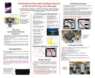
Tracker Calorimeter Tracker Calorimeter Charged Particle Detection vs. Backsplash A high-energy gamma ray can produce secondary photons that “splash” out of the CAL and can trigger an ACD tile. Charged particles produce signals lined up in the segmented ACD, TKR, CAL If the ACD were not segmented, we would lose the valuable high-energy gamma rays that produced a back-splash signal. This self-veto reduced the EGRET efficiency at high energies by more than 50%.
Level III Key Requirements Summary Reference: LAT-SS-00016
Meeting the Key Requirements For high-efficiency MIP detection (0.9997), want a low energy threshold. For good rejection of backsplash, want a high energy threshold. A good balance between these requirements is about 0.3 of the MIP peak energy. Backsplash + noise Charged Particles (MIP) Energy
Flowdown - Requirements to Design Note that each requirement is a constraint on the other. Note that each requirement is in tension with the other.
Evolution of the ACD Design Proposal Design 145 tiles, 290 phototubes each with HVBS Stand-alone electronics (ASIC/FPGA/ADC) Processed signals sent to LAT electronics Little mechanical support for electronics Current Design 89 tiles, 8 ribbons, 194 phototubes, redundant HVBS for each 18 phototubes Front-end electronics (ASIC/ADC) Little processing of signals sent to LAT electronics Realistic mechanical support for electronics
ACD Optimization - Summary • Light Collection - optimized with 5 mm fiber spacing, TETRATEC wrapping material, aluminized fiber ends, multiclad fibers. Scintillator manufacturer does not matter. Two sets of interleaved fibers for redundant readout. • Absolute Efficiency - using the light collection described above, a single phototube meets the 0.9997 efficiency requirement at 0.3 MIP threshold if there are no appreciable light losses. Light losses in long waveshifting fibers or connector to clear fibers makes the single tube marginal. Fibers were re-routed to shorter paths. With two tubes operating, there is ample margin. The top center row of tiles was thickened to give more light. • Broken Fibers - the ACD could meet its requirements with up to two broken fibers on all tiles. • Segmentation - the 89-tile design meets the backsplash requirements. • Hermeticity - a triple layer of square 1.5 mm fibers with offset centers provides adequate sealing of the gaps between tiles. Overlaps were increased to allow for vertical gaps required by acoustic loads. • REFERENCE: LAT-TD-00438-D2
ACD Technical Heritage • Plastic Scintillator - used in all previous gamma-ray telescopes OSO-3, SAS-2, COS-B, CGRO (all 4 instruments), plus many cosmic ray experiments. • Waveshifting fibers - used in GLAST LAT Balloon Flight Engineering Model (BFEM). Waveshifting bars used by HEXTE on RXTE (same material in a different geometry) • Photomultiplier tubes - used in all previous gamma-ray telescopes. HEXTE/RXTE used a commercial version of the same tube we are using (Hamamatsu 4443), and GOLF on SOHO used the same tube as the ACD except for the cathode material (Hamamatsu 4444) • High Voltage Bias Supplies - used in all previous gamma-ray telescopes, plus many cosmic ray experiments. • Electronics - similar ASIC’s (same designer) used on the BFEM. Discriminators, PHA and logic signals similar to many flight instruments. • Micrometeoroid Shield - Improved version (more layers, stronger materials) of shield that protected EGRET successfully for nine years.
Reviews – Past and Future • Past Reviews: • LAT Internal Review of the ACD – January, 1999 • Pre-PDR/Baseline Review – February, 2001 • LAT System Requirement Review (SRR)- May 2001 • ACD Peer Review – July, 2001 • 62 RFA’s – All closed out • LAT PDR/Baseline Review – January, 2002 • 12 RFA’s – All closed out • LAT Internal Stanford Linear Accelerator Center Review - April, 2002 • LAT Delta PDR/Baseline Review - July, 2002 • 3 RFA’s – All closed out • Future Reviews: • LAT Critical Design Review (CDR) - April 2003 • ACD Pre-Environmental Review (PER) – March 2004 • ACD Pre-Ship Review (PSR) – June 2004 • LAT Pre-Environmental Review (PER) - February 2005 • LAT Pre-ship Review (PSR) - July 2005
Summary of July Delta-PDR Review “Subsystem managers have done a very good job of getting the Anti-Coincidence Detector(ACD) ready for this review. All the recommendations from the January 2002 DOE/NASA review were addressed. In particular, a new bottoms-up Work Breakdown Structure was created, contingency and critical path analyses were performed, and Basis of Estimate was provided. Technical progress has been made on three fronts: • R&D was continued to finalize layout of the scintillator tile geometry. • New data was collected during test-beam at CERN to measure backsplash effect (self-veto of gamma events). • Full size mock-up of ACD was built at GSFC to work out details of fiber routing.”
Status of January Review Recommendations 1. Finalize the design and generate the engineering drawings for the tile and fiber layout, including the lowest row of the ACD. • Designs for the 12 types of tile have been analyzed for thermal and vibration tolerances. Results are being used to generate engineering drawings. • Design for the lowest tile row has been tested and shown to exceed the requirements. • Drawings have been made for the routing of the fibers from the tiles to the phototubes. The routing has been checked using a mock-up of the ACD Prototype tile for the lowest row of the ACD. Testing shows that this design exceeds the 0.99 efficiency requirement.
Status of January Review Recommendations 2. Perform light yield tests and muon detection efficiency measurement of the final optical system (scintillator tiles; and fiber ribbons, connector, clear fibers, and photomultiplier tubes). Complete – results are similar to those shown in January: with two phototubes, 0.9997 efficiency is met; with one phototube, efficiency is ~ 0.999 Light output of Fermilab tiles is good. Light losses in the optical connector and clear fibers were higher than expected. Design improvements were made to compensate for these losses. LAT-TD-00843-D1, Design Qualification Tests for ACD TDA and Phototubes Performance of a full end-to-end TDA
Status of January Review Recommendations 3. Demonstrate that electronic noise of the system is low enough not to affect the muon rejection efficiency and efficiency for gammas by more than one percent. • Bench tests of the first analog ASICs show no noise problem. Tests on a prototype electronics set (GAFE2 + GARC1) show good separation between MIP and noise signals. • The ACD electronics noise is required to be < 0.2 X threshold. The early calculations show that the noise at the lowest threshold setting of 0.1 MIP is approximately 50% lower than the requirement. • The ACD team along with the LAT Electronics Systems Engineers have developed a grounding and shielding design to keep noise to a minimum. PHA distribution from qualification phototube, resistor network, GAFE, GARC, and ADC.
Status of January Review Recommendations • Complete full mockup of ACD, including clear fiber layout to photomultiplier tubes. The mockup has been built and fiber routing placements have been completed. Full-scale mock-up of ACD being used for tile placement and fiber routing from tiles to phototubes. Two bottom tile rows have been included. Details of mock-up.
Status of January Review Recommendations • Perform thermal cycle of fully assembled tiles and ribbons. Verify that no damage to tile/fiber assemblies takes place and light yield is not decreased. • Thermal cycle was -65 C to +45 C. • Performance was measured using a muon telescope for Minimum Ionizing Particles. • After > 340 cycles, the loss of performance was less than 5%. LAT-TD-00858-D1, ACD TDA Thermal Cycling Test Light yield of Tile/fiber assembly during thermal cycling.
Status of January Review Recommendations 6. Prepare a plan for Quality Control (tile response uniformity and broken fibers) and initial calibration (ADC/minimum ionizing particle) of the ACD system prior to the delivery to the Stanford Linear Accelerator Center. • Quality Control is covered by the general ACD Quality Plan (ACD-QA-8001). • The methods for determining tile response uniformity and detecting broken fibers are documented in “Light Collection/Optical Performance Tests” (LAT-TD-00438-D2). Performance is measured using a muon telescope for Minimum Ionizing Particles. • A plan for calibrating the ACD using a muon telescope for mapping reference efficiency and then using internal triggers for PHA distributions is described in “ACD Gain Calibration Test with Cosmic Ray Muons” (LAT-TD-00844-D1). This approach was tested using the balloon flight ACD. • Quality plans and acceptance tests for the Tile Detector Assemblies and phototubes have been developed: “ACD Phototube Quality Plan and Acceptance Tests” (LAT-TD-1202), “ACD Tile Detector Assembly Quality Plan and Acceptance Tests” (LAT-TD-1203).
PAD FRAME OF TANNER I/O CELLS LVDS CELLS SIGNAL ROUTING TO PAD FRAME LOGIC CORE VDD RAIL GND RAIL Status of January Review Recommendations 7. Additional time should be added to the ASIC production schedule to provide some schedule margin. • The current LAT extended schedule incorporates an additional month for ASIC development and additional testing time. • The GSFC Program management approved qualification and screening process for the ASICs is now shorter than the original one. • The analog ASIC remains a critical path in the schedule. GARC Layout GAFE Veto Generation – 1 MIP
Status of January Review Recommendations 8. Complete the bottoms-up Work Breakdown Structure (WBS) in the Primavera framework. This include a WBS Dictionary and full Basis of Estimate. More than 800 activities in our resource loaded schedule. • The WBS has been completed and has 10 major elements: • 4.1.6.1 Project Management/Systems Engineering/Science • 4.1.6.2 Safety and Mission Assurance • 4.1.6.3 Tile Shell Assembly • 4.1.6.4 Base Electronics Assembly • 4.1.6.5 Micrometeoroid Shield/Thermal Blanket Assembly • 4.1.6.6 Mechanical Qualification and Calibration Unit • 4.1.6.7 Integration and Test • 4.1.6.8 LAT Integration and Test Support • 4.1.6.9 Mission Integration and Test Support • 4.1.6.B Ground Support Equipment and Facilities
Status of January Review Recommendations • Perform the critical path schedule analysis for the entire subsystem. Provide detailed documentation (at the lowest level of WBS) for the Basis of Estimate of the costs, in particular the on-project and off-project labor costs. Two critical paths have been identified (details in a later slide): • ASIC development and testing. Four iterations of the analog ASIC is scheduled. Turnaround time from submittal to delivery is typically at least 12 weeks. Adding testing time means that one iteration can take at least four months. Shortened time for the screening testing helps. Scheduled ACD delivery is 9 weeks before the LAT integration need date. • Photomultiplier tube delivery and assembly. The 6-month schedule extension alleviated that pressure somewhat, but the need to have a full set of tubes before assembly still makes this schedule fairly tight. A detailed Basis of Estimate is available. Summaries in later slides.
Status of January Review Recommendations • Perform the contingency analysis of the subsystem. In particular, assess contingency for the off-project labor tasks. A detailed contingency analysis, including all aspects of the ACD, has been carried out and incorporated into the PMCS. Some examples of contingency are shown in later slides.
Status of January Review Recommendations 11. Due to lack of a verifiable Work Breakdown Structure (cost estimate) for the ACD, the subsystem is not ready to be baselined at the present time. Consider the following streamlining steps: • Separate materials and services from the labor tasks at lowest WBS level • Identify all the off-project labor costs at the lowest WBS level • Use the actual, fully loaded costs for technicians, specialists, engineers, etc., in all WBS labor estimates • The PMCS contains this detailed information. Each resource is identified. Summaries are presented in later slides. • Because the Goddard tax system is based on estimates rather than actuals, the labor costs are not fully loaded. • Conduct a Subsystem Baseline Review as soon as the work on the subsystem Work Breakdown Structure is completed. Review was successfully completed in July.
Status of July ΔPDR Review Recommendations • Develop detailed specifications for the readout fibers (light yield, attenuation length, batch-to-batch variations) prior to the bid process and purchase of materials. • Material specifications and acceptance requirements are included in the contract with Fermilab, “Fabrication and Assembly Procedure for the Anticoincidence Detector (ACD) Tile Detector Assembly (TDA)”, ACD-PROC-000059. Performed light attenuation measurements on readout fibers from two different manufactures. • Ensure that the second generation of the analog ASIC, (to be delivered in August 2002) is well evaluated before third generation is sent off to production. • Testing showed problems with the second generation analog ASIC. The third generation, GAFE3, is being tested now, and a fourth generation, GAFE4, is due back later this month. • Continue to develop calibration plan for ACD for the Integration and Testing phase. • We are continuing to refine the calibration plan, building on our experience with laboratory testing. Example: ACD Functional Test Plans (Comprehensive Performance Test) LAT-TD-01112-D1
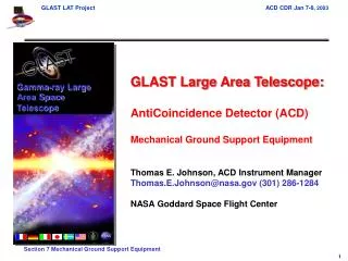
Gamma-ray Large Area Space Telescope GLAST Large Area Telescope: AntiCoincidence Detector (ACD) WBS 4.1.6 Management Thomas E. Johnson, ACD Instrument Manager Thomas.E.Johnson@nasa.gov (301) 286-1284 NASA Goddard Space Flight Center
Outline • ACD Team Leads • ACD Team Partners • Contingency • ACD Organization Chart • Work Flow • Testing Overview • Fabrication Plan • Schedule • Cost • Procurements • Configuration Management • Micrometeoroid Shield • Issues and Concerns • Summary
ACD Team Leads • Dave Thompson – Scientist, ACD Subsystem Manager • Bob Hartman – Scientist • Alex Moiseev – Scientist • Tom Johnson – Instrument Manager • Mike Amato – Systems Engineer • Ken Segal – Lead Mechanical Engineer • Glenn Unger – Lead Electrical Engineer • Jim La – Integration and Test • Carlton Peters – Thermal Engineer • Andy Eaker – Scheduler • Deanna Adamcyzk - Resources
ACD Team Partners • Micrometeoroid Shield – Johnson Space Center • NASA Center of Excellence for micrometeoroid protection • Eric Christiansen and Jeanne Crews • Tile Detector Assemblies – FermiLab (Department of Energy) • Experts in fabrication of scintillator detectors • Phyllis Deering and Todd Nebal • Scintillating Fiber Ribbons – Washington University, St. Louis • Leaders in scintillating fiber production • Professor Robert Binns • ASICs - Stanford Linear Accelerator Center (SLAC) • Extensive experience in ASIC design • Gunther Haller, Oren Milgrome, Dietrich Freytag
Contingency • All contingency (mass, power, cost) held at the LAT project level. Change requests are required to account for variance. • ACD Change Requests Submitted
ACD Subsystem 4.1.6 Dave Thompson, Subsystem Manager ACD management 4.1.6.1 Tom Johnson, Manager Deanna Adamczyk - Financial Resources Andy Eaker - Scheduling Ground Support Facilities & Equipment 4.1.6.B Jim La, Lead ACD Organization Chart ACD Design and Science Support 4.1.6.1.3 Alexander Moiseev,Lead ACD Systems Engineering 4.1.6.1.2 Mike Amato, Lead ACD Reliability and Quality Assurance 4.1.6.2 Patricia Huber, Lead Tile Shell Assembly 4.1.6.3 Ken Segal, Lead Base Electronics Assembly 4.1.6.4 Glenn Unger, Lead Micrometeoroid Shield / Thermal Blanket 4.1.6.5 Tom Johnson, Lead Carlton Peters, Thermal Lead Hardware Integration & Test 4.1.6.7 Jim La, Lead Mission Integration & Test Support 4.1.6.9 Bob Hartman, Lead LAT Instrument Integration & Test Support 4.1.6.8 Jim La, Lead Tile Detector Assemblies 4.1.6.3.2 A. Moiseev, Lead
ACD Work Flow Overview Tile Shell Assembly (TSA) Tile Detector Assemblies 11/03 Tile Shell Assembly 12/03 Shell 07/03Subassembly ASIC 10/03 Development Front End Electronics Card Assembly 11/03 Base Electronics Assembly (BEA) High Voltage Bias Supply 11/03 Base Electronics Assembly 03/04 ACD Performance and Environmental Test 07/04 Electronics Chassis 02/04 ACD Integration 03/04 Photomultiplier tubes 11/03 Ship 08/04 Base Frame 07/03 Subassembly Thermal Blanket Micrometeoroid Shield 01/04 Completion Dates Shown
ACD Testing Overview • Due to size and cost, there is no full-size ACD Engineering Model. The full-size mechanical mockup is used only for fit checks and fabrication of the micrometeoroid shield/thermal blankets. • Acceptance and Qualification tests, including performance, vibration, EMI/EMC, and thermal vacuum, are carried out at the component and subassembly level. Extrapolation to the full ACD is done by analysis. • The full protoflight ACD will undergo a complete suite of tests, including absolute efficiency measurement as well as all environmental tests. Subassembly vibration testing – a section of support shell, composite flexures supporting a scintillator tile, and a micrometeoroid shield/thermal blanket. A similar test included the waveshifting fibers, optical connector, optical fibers, and phototubes.
Development Testing Overview Vibration testing – a section of support shell, composite flexures supporting a scintillator tile, and a micrometeoroid shield/thermal blanket. A similar test included the waveshifting fibers, optical connector, and optical fibers. ACD-PLAN-000032, LAT-ACD Tile Detector Test Vibration Test Plan Thermal Vacuum testing – a section of support shell with composite flexures, three Tile Detector Assemblies, and four PMT/RN assemblies were exposed to 6 thermal vacuum cycles. ACD-PROC-000068, TDA-PMT-Resistor Network End-to-End Thermal-Vacuum Test Procedure Vibration testing – 4 PMT/RN assemblies with clear fibers connected to 3 TDA’s (not vibrated) were subjected to vibration testing.
ACD Fabrication Plan • Tile Detector Assemblies • Fermi Lab • Composite Shell • Panel fabrication performed by outside vender, assembly and test in house • Base Frame • In house fabrication, assembly and test • Analog and Digital ASIC’s • GSFC/SLAC Design, MOSIS fabrication, GSFC acceptance testing • High Voltage Bias Supplies • In house design, fabrication by local vender, testing in house • PMT/Resistor Network Assembly • Procure components and assemble and test in house • Front End Electronic (FREE) Boards • Procure components and assemble and test in house • Micrometeoroid Shield/Thermal Blanket • Shield designed by JSC, Blanket designed by GSFC, In house fabrication • ACD Integration and Test • Building 7, 10, 15, & 29 complex Qualification phototube in housing with resistor network.
Procurements • Long lead procurement • Photomultiplier Tubes – Have received 90 flight tubes • Major upcoming procurements • Support Shell • Tile Detector Assemblies (with fibers) • Base Frame • Flight ASICs • High Voltage Bias Supplies • PMT Assembly • Smaller upcoming procurements • Electrical components • Tile Detector Assembly mounts Tile Detector Assembly with A clear fiber connector
Configuration Management & Information Technology • GSFC CM System • Next Generation Integrated Network – Secure Web based configuration management system. It is a full service CM system with the following services: • Release and electronically store drawings, procedures, documents, and Work Order Authorizations (WOA’s) • Action Item Database • Document Library • LAT CM System • Cyberdocs – Web based document storage. • ACD documents that involve the LAT (i.e. all interface and top level documents) will be placed on Cyberdocs • Lower level ACD Documents, Drawings, and WOA’s will be on the GSFC CM System • ACD Website: http://lhea-glast.gsfc.nasa.gov/acd/ • Website is used to share information and store draft documents – Used extensively prior to getting the CM system on-line
Micrometeoroid Shield Design • Purpose: To prevent light leaks in Tile Detector Assemblies due to micrometeoroid penetrations • Analysis and Testing being performed by Johnson Space Center (Eric Christianson & Jeanne Crews) • LAT-TD-1122.1 – “ACD Micrometeoroid Shield Analysis and Design” • Current Design based on ORDEM96: (1) Nextel AF10 (1) Nextel AF10 3.27cm max (1) Nextel AF10 (1) Nextel AF10 (6) Kevlar KM2
Micrometeoroid Shield Requirements • Requirements are being updated. ORDEM2000 is replacing ORDEM96
Micrometeoroid Shield Testing • To measure the difference between models, we took a thermal blanket and wrapped tile with a phototube to Houston (Rice University), combined it with a flight-design shield, and tested it using high-velocity particles at their test facility. • Testing particles and shields of several sizes, we determined that the existing shield design needs to be improved to enable the Micrometeoroid Shield to achieve its required 95% PNP over 5 years. • Re-design has been approved (estimate ~$25K).Waiting on final requirements flowdown from GLAST and LAT before proceeding. Light gas gun, operated by JSC at Rice University. We tested ~2 mm Al particles at 7 km/s. Damage to the interior part of the shield from a 2.2 mm particle. The hole is about 30 mm diameter. The Kevlar backing sheets stopped the debris (this time).