Download
1 / 16
160 likes | 235 Views
Results from the HV Test System. J. Long, P. Barnes, J. Boissevain, J. Gomez, S. Lamoreaux, D. Mischke, S. Penttila LANL. Review of current design and assembly. Results with normal state LHe. Cool-down and heat loads. Amplification and large-gap E-fields. Leakage currents.

E N D
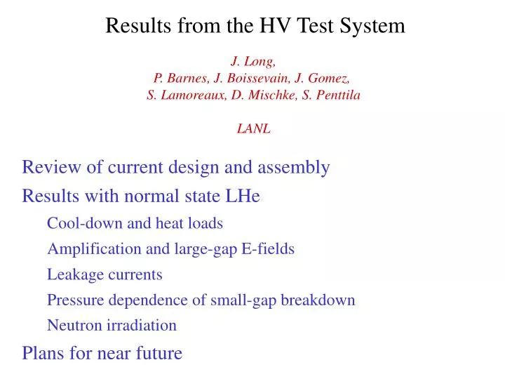
Results from the HV Test System J. Long, P. Barnes, J. Boissevain, J. Gomez, S. Lamoreaux, D. Mischke, S. Penttila LANL Review of current design and assembly Results with normal state LHe Cool-down and heat loads Amplification and large-gap E-fields Leakage currents Pressure dependence of small-gap breakdown Neutron irradiation Plans for near future
Electric Field: LHe Breakdown vs Gap extrapolation (?) 50 kV/cm 76 mm Figure: J. Gerhold, Cryogenics 38 (1998) 1063 Need 50 kv/cm across 8 cm cell ~ 400 kV Internal amplifier (avoid heat loads, large feedthroughs) Variable capacitor with C >> Ccells ~ 50 pf
Design: vacuum enclosure supply cryostat LHe reservoir LN2 reservoir vacuum chamber 77 K shield ~2 m air-vacuum HV feedthrough linear actuator LHe vessel G-10 foot Vacuum pump, T- sensor readout attachments
Assembly: central volume View of electrodes through side port Leak check of central volume and bellows
Assembly: vacuum system LHe vessel in Kevlar sling Complete system showing HV charger drive rod, linear actuator and motor 20 layers superinsulation
transfer tube LHe vessel LN2 plug Cooling and filling of central volume (December 2003) Temperature sensor locations 1 4 2 5 3 3 days to fill from room temperature start (limited by Cu shield), need ~ 400 liters of LHe
Heat loads Estimated sources Measurement Supply cryostat neck 1800 mW Average He gas boil-off: (flowmeter near 300 K) 52 liters/min (Neck with 77 K anchor) (770 mW) 3.4 liters/hr 4 K liquid boil-off: Radiation through SI 725 mW (?) Total load: 2660 mW Unshielded quartz windows 30 mW Kevlar rope suspension 10 mW Ground actuator/spider 10 mW Estimate after restoration of 77 K anchor: 1600 mW HV actuator/spider 5 mW HV conductor 2 mW Temperature sensors 1 mW 2585 mW (1555 mW)
Amplification Measurement: Meter on Charger First attempted load cell on actuator: P = e0E2/2, Unrepeatable backgrounds at 4 K HVPS 50 kV CHC CHG CHF CCF CCC Q • Use SR570 current amplifier • Readout with ADC at 130 Hz
Readout SR570-A CURRENT PREAMP RG8 - BNC GAMMA 50 kV 1.25 mA HVPS TERMINAL STRIP 64 RG8 7m 500 pF NI-PCI 6024e ADC THOMSON DRIVE # CDM010i RS-232 OMNI- LINK PC LabVIEW 10 MW THOMSON MOTOR 360 W ~ 4500 N max GPIB LAKESHORE 218 16
HV-Charger Capacitance Close HV-G gap Monitor C with bridge on 100 kV feedthrough as increase Charger-HV separation C0 A z0 Charger retracted to 4.24 cm where CHC = 1.6 ± 0.2 pF
Largest Potentials Attained 2/25/04 11:00, step G from 2.5 to 73 mm, initial potential = 42 kV Pull back G electrode at constant 1inch/min Shape should track dV/dz : Expect initial current (first 2.5 mm pullback): ~ 12 nA (z0 ~ 5 cm)
Largest Potentials Attained 2/25/04 11:00, step G from 2.5 to 73 mm, initial potential = 42 kV = 862 nC VHG(7.3 cm) = (570 ± 70) kV CHC error 13% SR570 zero drift 3% transients 2% 2/20/04 22:15, step G from 2.5 to 73 mm, initial potential = -31 kV Charging with negative potential: • Draws steady current > 50 mA below –30 kV • Current independent of charger position VHG(7.3 cm) = (-360 ± 60) kV
Leakage Current 2/20/04 23:15, step G out to 7.3 cm initial potential = 29 kV 2/21/04 10:47, return G to 3 mm gap QHC = 568 nC QHC = 566 nC (EHG = [52 ± 8] kV/cm) CHG = 53 pF (bridge, ± 5%) _ CHC = (1.6 ± .2) pF iLEAK = (-2 ± 20) pA DQHC = (-2 ± 24) nC (3% zero shift) Dt = 11h 32 min ± 5 min
Breakdown vs. Pressure – 3 mm gap Pump LHe bath with roots blower (250 m3/hr) ~ 8 psi check valve limits pressure Could reduce to 25 kV/3 mm (300 kV/ 7.3 cm) or worse at low P 2/27 data (open circles): • System had 2 additional days at 4 K • 5 hr after LHe top-off • 30 min. prior HV conditioning
Radiation Effects ~ 7 Ci n-source, 50 cm from gap, nearly on-axis Small gap (3 mm), 30 minutes after LHe fill, ~ 5 minutes conditioning, 1 psig Slight improvement (or conditioning) Large gap (maintained for 1 minute, no plexiglas, inward trace shown): VHG(7.3 cm) = (390 ± 60) kV
Conclusions (570 ± 70) kV 73 mm Large wire-seal flanges hold LHe (thermal gradients > 60 K / 60 cm) Next steps Normal State LHe holds 570 kV at 7.3 cm (~ 40% higher than “expected”) Superfluid operation (either way…) Design field at 7.3 cm holds for > 11 hr E-field measurement via Kerr effect (Discussions with UC…) Max leakage current = 20 pA (~ 3% of tolerable limit) Problem with low-P operation? Prototype holding cell (Lucite, coatings…) behind HV electrode Small gap breakdown not affected by neutron radiation (106/s, ~MeV)