Download
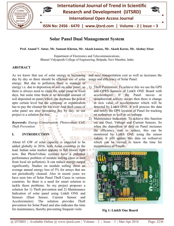
1 / 18
190 likes | 547 Views
MSU Solar Team Battery Management System. Team 7 Matt Gilbert- Eyres , Albert Ware Gerald Saumier , Auez Ryskhanov Michael Burch Facilitator Dr. Bingsen Wang. Table of Contents. What Is A Battery Management System Cell Protection Communication Design Budget Status/Goals.

E N D
MSU Solar TeamBattery Management System Team 7 Matt Gilbert-Eyres, Albert Ware Gerald Saumier, AuezRyskhanov Michael Burch Facilitator Dr. Bingsen Wang
Table of Contents What Is A Battery Management System Cell Protection Communication Design Budget Status/Goals
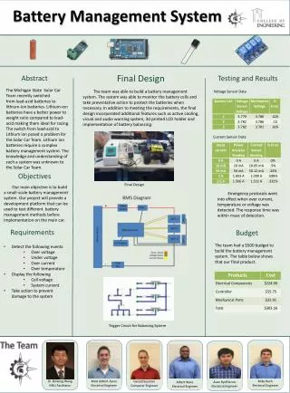
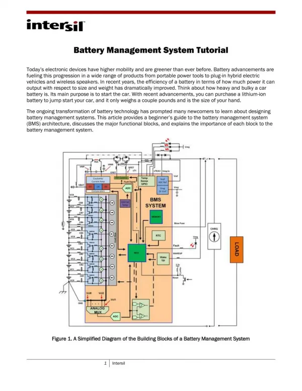
What Is A Battery Management System? • Electronically controlled system that manages rechargeable battery cells. • Four Functions • Cell Protection • Cell Balancing • State of Charge • Communication
Design Layout • General layout of the system and it features
Communication Requirements • Communication Board • 8 analog inputs • 4 analog outputs • Display Screen • Compatible with chosen board • Possible touch screen for input to system • Sensors • 4 voltage sensors • 1 current sensor • 3 temperature sensors
Communication Board & LCD Screen Arduino Mega 2560 R3 • 16 Analog Inputs • 16 MHz Clock Speed • 256 KB Flash Memory • ATmega2560 Microcontroller LCD Touch Screen • 3.2” LCD Touch Screen • 5V Operation Voltage
Cell Protection: Sensors • Voltage Sensor (4) • 0.02445-25V input voltage detection range • 0.00489V voltage analog resolution • Reduces voltage 5x for input to Arduino • Current Sensor (1) • AC/DC compatible • Hall Effect • -50A to 50A current range • Temperature Sensor (3) • Thermistor Based • Approx. -40º C to 125º C range
Cell Protection: Cooling System • 2 Fans to cool down the batteries • 1 Fan to cool down the Arduino board
Battery Balancing • Protects the system by balancing the cells to compensate for the differences. • Increase efficiently of system and life of battery • Team currently use passive balancing • Implementation of active balancing
Passive Balancing • Higher voltage batteries are connected to resistors to lower voltage (balance the cells). • High Losses • Easy to use
Active Balancing • Move charge from a higher voltage cell to one with the lower charge.
System Fusing • Fuse type: 10Amp 32 Volt Micro2 Fuse by Littelfuse. • Purpose for fusing the system is to ensure wires and the system are protected in a over current situation.
System Wiring • Wire size was based on current and voltage requirements. • For our project we will be using 18 gauge wiring (.82mm^2)
Packaging Figure1: BMS Housing Figure2: Battery Box Figure3: Battery Holder
Motivation • ElithionLithiumate Pro • Balancing • Charge Control • Price
Status/Goals • Design aspect is complete • Currently waiting for Parts • Going into the design/prototyping phase • Looking forward to the balancing mechanism
Thank You Questions?