Download
1 / 44
440 likes | 551 Views
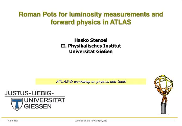
Roman Pots for luminosity measurements and forward physics in ATLAS. Hasko Stenzel II. Physikalisches Institut Universit ät Gießen. ATLAS-D workshop on physics and tools. Messung der Luminosität - Motivation.

E N D
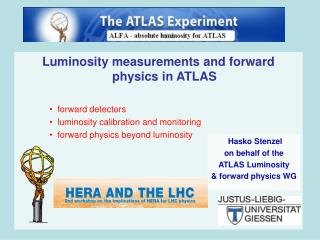
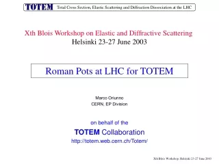
Roman Pots for luminosity measurements and forward physics in ATLAS Hasko Stenzel II. Physikalisches Institut Universität Gießen ATLAS-D workshop on physics and tools Luminosity and forward physics
Messung der Luminosität - Motivation • Präzise Messungen der Wirkungsquerschnitte (x Branching ratio) für Standardmodellprozesse wie • t-tbar,b-bar Produktion • W/Z Produktion • QCD jets Untergrund für Searches, Bestimmung von PDFs Die Genauigkeit theoretische Vorhersagen liegt bei 5-10%, wird jedoch zunehmend besser (NNLO, PDFs). • Suche nach neuer Physik in der Abweichung von x BR relativ zur SM Vorhersage • Wichtig Messungen von SM/MSSM Parametern • Higgs Produktion x BR • tan Messung für MSSM Higgs Luminosity and forward physics
Relative precision on the measurement of HBR for various channels, as function of mH, at Ldt = 300 fb–1. The dominant uncertainty is from Luminosity: 10% (open symbols), 5% (solid symbols). (ATLAS-TDR-15, May 1999) Impakt der Luminositäts Messung Beispiele Higgs Kopplungen tan Messung Systematic error dominated by luminosity (ATLAS Physics TDR ) Luminosity and forward physics
ATLAS Strategie zur Lumi-messung • Angestrebte Genauigkeit ΔL= ±2-3% • Relative Luminosität mit einem dedizierten luminosity monitor LUCID , linear über einen dynamischen Bereich von 1027 – 1034 cm-2 s-1 , ggf. unterstützt durch andere Detektoren (Tile, Larg, BCM...) • Absolute Luminosität • Kalibration über elastische Streuung im Coulomb-Bereich mit spezieller Strahloptik bei L= 1027 cm-2 s-1 und Roman Pot Detektoren • Mit dem Optischen Theorem: elastische Vorwärts- + total inelastische Rate: Roman Pots+central detector • |η|-coverage in ATLAS ist jedoch begrenzt • Unter Verwendung von tot z.B. von TOTEM • Kombination der Maschinen-Luminosität mit dem optischen Theorem • Aus den Raten von präzisen Eichprozessen wie • QCD pp→W/Z • QED γγ→µµ • Aus den LHC Machinenparametern • Unter Verwendung eines Null-Grad Kalorimeters in Schwerionenkollisionen in ATLAS werden alle Optionen verfolgt! Luminosity and forward physics
Elastische pp Streuung in der Coulomb Region dN/dt Roman-Pot Messung • Aus einem fit an das gemessene t-Spektrum in der Coulomb Region können wir die Parameter • tot ,ρ, b and L • bestimmen. Luminosity and forward physics
Messung der elastischen pp Streuung • Zwei Roman Stationen auf jeder Seite 240m vom ATLAS IP entfernt • Ein scintillating fibre tracker zur Messung des t-Spektrums elastisch gestreuter Protonen • Spezielle Strahloptik mit grossem β* und parallel-to-point Fokussierung • Absolute Kalibration bei L=1027cm-2s-1 • Relative Luminositätsmessung bei L=1027cm-2s-1 -1034cm-2s-1 mit LUCID Luminosity and forward physics
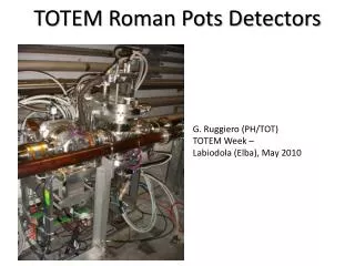
Roman pots für ATLAS Roman Pots Luminosity and forward physics
Roman Pot Mechanik Design des Positionierungs- und Vakuum- Systems gemeinsam mit TOTEM Luminosity and forward physics
Roman Pot – Vakuum-Kammer und Detektoren Vakuum-Kammer Szintillierende Fasern in UV-Geometrie Luminosity and forward physics
Scintillating fiber tracker • Überlapp Detektor • Messung des vertikalen alignment • 3 Module mit 60 x-Fasern • Halo Trigger Szintillator • Trigger Szintillator • Szintillierende Fasern • Kuraray 0.5 mm× 0.5 mm fibers single cladded, verspiegelt • 10 Module mit 64 U/V Fasern, double sided • 70 μm Versatz zwischen den Modulen Ceramic spacers (0.5mm thick) Ceramic substrate (170mm thick UV planes 90˚ and 45˚ end cuts Luminosity and forward physics
MAPMT MAPMT MAPMT MAPMT MAPMT SciFi Elektronik Motherboard : Data serializer (FPGA) , Optical Transmission, TTC, monitor, Voltage reg. TTC HV LV Trigger Data Kapton cable & Connectors Mother board PMT Backend : one chip per PMT, pipeline latency for L1, parallel to serial data FE FE FE FE FE 1 or 2 ASICS per PMT PMT Frontend : one chip per PMT,gain adjustment, discriminator (64 channels) PMTs : 5x5 array of 64 anodes MAPMT, H7546B Hamamatsu Luminosity and forward physics
Projektstatus • Prototypentwicklung bis Mitte 2006 • Protoyp0 wurde im Labor getestet/vermessen • Prototyp1 (10 Module / 6 Fasern + 2 Module / 32 Fasern) wird im Okt/Nov am DESY testbeam getestet: Auflösung, Lichtausbeute, FE-Elektronik • 2006 Modul0, Testbeam mit FE & Readout-Elektronik tests • Detektor Produktion 2006-2007 • Installation shutdown 2007/2008 • Lumi Messung Ende 2008 Prototyp0 DESY testbeam set-up Luminosity and forward physics
parallel-to-point focusing ydet y* y* IP Leff Experimentelle Bedingungen • Messung in der Coulomb-region, t=(θ▪p)2 • Unabhängig vom vertex offset: • Untere Grenze für |t|min: • Anforderungen • Detektor dicht am Strahl • grosses * • geringe Emittanz • Kontrolliertes Halo • Spezielle Optik, niedrige Lumi • Detektorauflösung ≈ 30 µ Luminosity and forward physics
Messung des t-Spektrums der elastische Streuung Photon exchange, coulomb region Photon - Pomeron interference r Multigluon (“Pomeron”) exchange e– b |t| ds/dt [mb / GeV2] t p2q2 diffractive structure High β* Optik für ATLAS pQCD wide range of predictions pp 14 TeV BSW model -t [GeV2] Luminosity and forward physics
Simulation der Detektorauflösung expect Npe/fibre ~ 3 confirmed with source tests Luminosity and forward physics
Simulation des dNel/dt Spektrums und Fit Ereignis Generation: • 5 M events generiert entsprechend ~90 hr bei L 1027 cm-2 s-1 • High β* - Strahloptik, 4-implulse -> Detektorhits • Keine systematischen Unsicherheiten (Alignment, Strahloptik,...) • Detektorsimulation für eine Roman-Pot Station Simple fit • Fit-Range: • 0.00056 < |t| < 0.030 GeV2 • ~4 M Ereignisse rekonstruiert for dN/dt Luminosity and forward physics
LUCID - der relative Luminositätsmonitor (“LUminosity measurement using Cerenkov Integrating Detector”) Projektive Alu Cerenkov Röhren um die beam pipe (200 pro Seite) Cerenkov radiator gas C4F10 ηMAX = -ln (tan 0.132º) = 6.073 ηMIN = -ln (tan 0.266º) = 5.374 Eingangsfenster ~ 17m vom IP Cerenkov-Licht über Quarzfasern an MAPMT Luminosity and forward physics
LUCID Prinzip • Sensitiv auf primäre Teilchen vom IP, unempfindlich auf sekundäre und weiche Teilchen • Projektive Geometrie • Kürzere Weglängen für gestreute Sekundärteilchen • Cerenkov-Schwelle für weiche Teilchen • Keine Landau Fluktuationen für Cerenkov Licht, single particle peak • Gute Impulshöhen-Auflösung, Messung von mehreren Spuren/Röhre • Keine Saturation bei höchster Lumi • Lineare Beziehung zwischen Lumi und Anzahl der Spuren • Ortsauflösung durch Position der 200 Röhren • Gute Zeitauflösung (~140ps @ CDF) • Bewährte Technologie - CDF • Strahlungshart, kompakte Anordnung zwischen Strahlrohr und forward shield Linear response No Saturation Luminosity and forward physics
Alternative Lumi-Messungen: W/Z produktion • Inklusive Produktion von W/Z Bosonen mit Zerfällen in isolierte Leptonen • Hohe Raten, klare Signaturen • Typische Schnitte für W: pTlept >25 GeV, |ηlept |< 2.5, ETmiss >25 GeV, lept.isol • Akzeptanz≈0.5 • Messung von N(W)xBR(We,µ+ν) • Theoretische Vorhersage für σ(W) • Systematische Unsicherheiten • ΔPDF? • ΔQCD? Luminosity and forward physics
Systematische Unsicherheiten σth(W) • PDF Unsicherheiten berechnet mittels der MRST/CTEQ family members • (30-40 Variationen der nominellen PDF) • CTEQ61 : Δ=± 5% • MRST2001 : Δ=± 2% • QCD Unsicherheiten abgeschätzt über Skalenvariation (µR, µF) • Δ QCD =+ 5 – 3.5 % (NLO) • =± 1% (NNLO) Luminosity and forward physics
Luminosität aus LHC Maschinenparametern • Luminosität kann aus den Strahlparametern bestimmt werden: • Bestimmung von L durch einen Van der Meer scan des vertikalen beam offsets Messung des beam currents Messung des beam profiles x z y yo x Bunch Dichtefunktinen können vop den Experimenten aus beam-gas Interaktionen gemessen werden! Luminosity and forward physics
Messung der beam-gas und beam-beam Vertices IP8 VD Gas Interactions IP3±2 Beam2-gas Beam1-gas Beam1-beam2 VD RP RP Gas Expt • Proposal: • Inject a tiny bit of gas (if needed at all!) into the vertex detector region • Reconstruct bunch-gas interaction vertices • get beam angles, profiles & relative positions • overlap integral • Simultaneously reconstruct bunch-bunch interaction vertices • calibrate ‘reference’ cross-section • Absolute Luminosity Genauigkeit < 5% Massimiliano Ferro-Luzzi Luminosity and forward physics
Vorwärts-Physik • Elastische Streuung • Totaler Wirkungsquerschnitt • Diffraktive Streuung (single, double Pomeron exchange ) • Austausch von farbneutralen Objekten • colour singlets (“Pomerons”) • rapidity gaps Δη Die Breite des rapidity gaps hängt mit dem Impulsverlust des Protons zusammen Δη≈-lnξξ=p-p‘/p p1 p1’ Dh1 P M P Dh2 p2’ p2 p • Austausch von colour triplets/octets • in minimum bias Ereignissen • rapidity gap exponentiell unterdrückt g, q M g, q p P(Dh) = e-r Dh, r = dn/dh Luminosity and forward physics
Optisches Theorem Der gesamte Wirkungsquerschnitt σtot COMPETE collaboration: Große Modell-Unsicherheit 90 – 130 mb [PRL 89 201801 (2002)] Luminosity and forward physics
Der ρ-Parameter Der ρ-Parameter hängt über die Dispersionsgleichung mit dem Wirkungsquerschnitt zusammen. Für LHC ergibt sich eine Vorhersage von (COMPETE): ATLAS plant σ, ρ, b und L aus einem simultanen fit an dN/dt zu bestimmen. Luminosity and forward physics
diffractives System M proton:p1’ proton:p2’ rapidity gap rapidity gap M hmin hmax Double Pomeron Exchange M Diffraktive Physik Produktion eines hadronischen systems M=ξ∙s mit einem rapidity gap und diffraktif gestreuten Protonen ds/dh proton:p’ diffraktives System M rapidity gap Dh =–ln hmin 0 hmax M1 M2 Luminosity and forward physics
Harte Diffraktion: • Diffraktive mit Ereignisse mit einem • harten partonischen sub-Prozess • Bestimmung der Pomeron-Strukturfunktion oder der Diffraktiven PDF e.g. jets, W, Z, b, J/Y, ... hard M hard hard Double Pomeron Exchange M Harte diffraktive Steuung Luminosity and forward physics
gap gap H p p -jet Exklusive Diffraktive Higgs Produktion -jet H Exklusive diffraktive Higgs produktion pp p H p : 2-10 fb Inklusive diffraktive Higgs produktion pp p+X+H+Y+p : O(100) fb dipole dipole p’ Messung des Impulsverlustes in Roman Pots be 420m (cold region) roman pots p’ Luminosity and forward physics roman pots
Exklusive Higgs Produktion im Standard Modell b jets : MH = 120 GeV σ = 2 fb (Unsicherheitsfaktor ~ 2.5) MH = 140 GeV σ = 0.7 fb MH = 120 GeV : S/B= 11/O(10) für 30 fb-1 und ΔM=3 GeV WW* : MH = 120 GeV σ= 0.4 fb MH = 140 GeV σ = 1 fb MH = 140 GeV : S/B = 8/ O(3) für 30 fb-1 • Highlights: • Klare Signatur und Redundanz durch Messung der Protonen und des Zentralsystems • Austausch eines colour singlets mit Quantenzahlen des Vakuums: • Auswahlregel: JP = 0+, (2+, 4+ ); C = +1 • Untergrund unterdrückt gg qq, bb • Test der Quantenzahlen des Higgs • P = (–1)J(+1) dσ/dΦ ~ 1 +(–) cos 2Φ • Bedingungen/offene Fragen: • Level1 Trigger, b-tagging, low luminosity • rapidity gap survival, background • Proton tagging (420m?) mit Impulsmessung Luminosity and forward physics
Exclusiv-diffraktive Higgs produktion im MSSM Beispiel-Rechnung von Martin, Khoze und Ryskin hep-ph/0507305 Luminosity and forward physics
Zusammenfassung • Optionen für die Luminositätsmessung bei ATLAS • Absolute Kalibration durch Coulomb Streuung • W/Z, γγ, ... Ratenmessung • L aus der elastischen Streuung dN/dt|t0 mit tot von TOTEM • LHC Maschinenparameter • weitere ... Angestrebte Genauigkeit ΔL= 2-3% • Dedizierte Detektoren • Roman Pot SciFi tracker zur elastischen Streuung • LUCID als Luminosity Monitor • Neue Detektoren FP420 R&D für forward/DPE Physik (upgrade) • Physikziele • Eleastische Streuung, Total cross section • Diffraktive Physik (Strukturfunktionen, rapidity gaps) • Exklusive harte Diffraktion (W/Z, jets, Higgs Produktion) Luminosity and forward physics
Backup transparencies Luminosity and forward physics
Participating institutes: (as a subsystem, fully part of the ATLAS collaboration) University of Alberta CERN Ecole Polytechnique Institute of Physics Academy of Science, Czech Republic University of Manchester University of Montreal University of Texas University of Valencia SUNY Stony Brook New candidates: Bologna (LUCID electronics) Giessen (RP SciFI) Cost Estimates & Participants Luminosity and forward physics
Use ZDC in heavy ion runs to calibrate machine instrumentation Luminosity and forward physics
Der Faserdetektor - Projektübersicht Zeitplan Kostenplan Luminosity and forward physics
Requirements to reach the Coulomb region • Required reach in t : • Requires: • small intrinsic beam angular spread at IP • insensitive to transverse vertex smearing • large effective lever arm Leff • detectors close to the beam, at large distance from IP Parallel–to–point focusing Luminosity and forward physics
Requirements for Roman Pot Detectors • “Dead space”d0 at detector’s edge near the beam : d0≲ 100m (full/flat efficiency away from edge) • Detector resolution: d = 30 m • Same d = 10 m relative position accuracy between opposite detectors (e.g. partially overlapping detectors, …) • Radiation hardness: 100 Gy/yr • Operate with the induced EM pulse from circulating bunches (shielding, …) • Rate capability: O(MHz) (40 MHz); time resolution t = O(1 ns) • Readout and trigger compatible with the experiment DAQ • Other: • simplicity, cost • extent of R&D needed, time scale, manpower, … • issues of LHC safety and controls Luminosity and forward physics
Design: Modules of 128 fibres glued on ceramic substrate 64 U-fibres top, 64 V-fibres bottom machining and metallisation of surface 10 modules per RP staggered by 70 µm 3 overlapp detectors Detector Construction • Production: • positioning technique using ceramic moulds • precision metrology for fibre position • single point diamond machining • sputtering of surface • gluing of fibres in optical connectors • Prototyping at CERN • Production in Giessen? Luminosity and forward physics
Integration in the Roman Pot Luminosity and forward physics
MAPMT: Hamamatsu R7600 64 channels 2.3 X 2.3 mm2 pixel surface 12 dynodes gain 106 - 107 20 % quantum efficiency MAPMTs and front-end electronics • Front-End: OPERA chip • gain adjustment • discrimination • line driver • Motherboard • trigger/timing cntrol • data transmission • voltage distribution Luminosity and forward physics
Simulated Elastic Scattering • Reconstruct θ*: Inner ring: t = -0.0007 GeV2 Outer ring: t = -0.0010 GeV2 Luminosity and forward physics
LUCID location Luminosity and forward physics
RP electronics - Radiations Front of Q7 quadrupole Rp section 102-103 Gy per year @ 1034 luminosity Luminosity and forward physics
RP electronics - Radiations 102-103 Gy per year @ 1034 luminosity 0.1-1 Gy per year @ 1027 luminosity 100 Krads per year to the (inactive) electronics and detector if left in place during normal runs 1 to 10 rads/year in operation (negligeable) Luminosity and forward physics