Download
1 / 36
360 likes | 521 Views
HOW TO DETERMINE LIE WATTAGE. LOAD 1 2 3. WATT RANGE _ W = 3 EI cos where E = 110V (rating) I = 5A (rating) When the cos equals 1, W will be given as 952.62. Considefing the operational function of E value, the watt range is 0 to 1000. 5A.

E N D
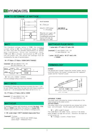
HOW TO DETERMINE LIE WATTAGE... LOAD 1 2 3 WATT RANGE _ W = 3 EI cos where E = 110V (rating) I = 5A (rating) When the cos equals 1, W will be given as 952.62. Considefing the operational function of E value, the watt range is 0 to 1000. 5A 5A OUTPUT 110V 110V SOURCE WATT WATTHOUR PULSE RATIO The standard voltage rating is 110V, the standard current rating is 5A, the transducer range is 1000W for 100% input with the standard specifications for 3phase watt transducers. Since the transducer input, 110V and 5A,is already transformed by PT and CT one the power line, the actual line wattage must be multiplied by the rate of transformation. W = PT Ratio x CT Ratio x 1000W (INPUT RANGE) [example] PT ratio:6600V/110V = 60 CT ratio:200A/5A = 40 W = 60 x 40 x 1000W = 2400kW The line wattage rating is then 0 to 2400kW. 1 pulse ratio = PT ratio x CT ratio x Wh [example] PT ratio:3300V/110V = 30 CT ratio:200A/5A = 40 1 pulse = 30 (PT ratio) x 40 (CT ratio) x Wh = 1200Wh TERMINOLOGY 110v • POWER The general term “power” means the “active” power, and in more strict terms, the “power” includes also the “apparent” power and the “reactive” power. • APPARENT POWER The power value calculated by simple multiplication of the rated voltage by the rated current. • ACTIVE POWER The power value to be converted into any energy form at the load. Unit is W (watt). The W is given with the equation : W = El cos (3-phase) The cosequals the power factor, cosine of the phase angle between voltage and current, therefore the equation is also given as: W = Voltage Current Power Factor 6600V PT WATT TRANSDUCER 1000W ? 200A CT 5A REACTIVE POWER (Var) APPARENT POWER(VA) WATT RATIO A standard 3-phase watt transducer accepts the input 110V, 5A and 1000W range.When the watt ratio with these conditions is given as 1, the acceptable Watt Ratio will be 0.5 to 1.2. W = PT Ratio x CT Ratio x 500 to 1200W [example] PT ratio:6600V/110V = 60 CT ratio:200A/5A = 40 ACTIVE POWER (W) = Phase angle between current and voltage WATTHOUR A standard 3-phase watt transducer accepts the input 110V, 5A and 1000W range.When the watthour is 1pulse/1Wh , mode is open collector or Dry-contact or Voltage pulse. • Wh pulse range = WATT standard range pulse/1hour [example] 3-phase INPUT range 110V,5A and 1000W range, pulse range = 1000pulse/1hour
REACTIVE POWER The power value which is not converted into energy. When the load has a greater inductive factor, more current is required for creating the same active power value. Unit is Var (volt-ampere reactive). The Var is given with the equation: Var = El sin • INPUT BURDEN The power value consumed at transformers at the primany side. Unit = VA = voltage rating current rating • OVERLOAD CAPACITY The rush current value, generated at start-up of a motor, allowable to the transmitter. WAVEFORM TYPE RMS MAD RMS/MAD CREST FACTOR Sinusoidal Waveform Vm 0.707 Vm 2 0.637 Vm = 1.111 2 = 1.414 DC Factor Vm Vm Ripple SquareWaveformorDC Vm Vm 1 1 Triangular Waveform Vm Vm = 1.156 = 1.732 Peak Average RMS Peak-to-Peak • HOW TO REPRESENT ALTERNATING POWER... An instantaneous value I alternating current/voltage varies according to time. In the other part, a peak value is not able to include effects by waveform distortion, while a simple average value calculation equals zero. The following are examples for re presenting alternating current/voltage. • PEAK VALUE The maximum value in the waveform. • PEAK-TO-PEAK VALUE The absolute value between the positive peak value and the negative peak value. • RMS(root-mean-square) VALUE The square root of the average of the squares of the instantan eous value. This AC power are able to generate the same heat (energy) as the same DC power value. • AVERAGE VALUE (in alternating current) The average of absolute value. • RIPPLE AC factor existing in a transmitter output. Represented as peak-to-peak value or as RMS value. Ripple is represented with “peak-to-peak” value or “r.m.s” value RMS SENSING & AVERAGE SENSING 0 Vm 0 0 The crest factor indicated in the above in the above table is given from the peak value divided by RMS value. It means the r.m.s value is stable in any waveforms. The ratio value [RMS/MAD] in sinusoidal waveform equals 1.111, Therefore by multiplying the average value by 1.111, an accu rate output is given in average sensing, while there will be a significant difference in other type of waveforms such like a thyristor output.
HD POWER TRANSDUCER SERIES AMPERE TRANSDUCER MODEL HDA - MODEL & SUFFIX CODE SELECTION HDA MODEL • INPUT • OUTPUT • MODE INSTALLATION Operating temperature : -5 to +55C Operating humidity : 20-80%RH(non-condensing) Mounting : Wall or DIN rail Power supply : AC 110V or 220V (-15/+10%) 50/60Hz,2VA Size : W75 H75 D113mm Weight : ORDERING INFORMATION Specify code number and variables * Code number : HDA-input/output/mode ex : HDA-2AR * special output range : A = -10~20mA V = -10~12V INPUT & OUTPUT GENERAL SPECIFICATIONS • INPUT input : 0-1A AC or 0-5A AC Operational range : 0-120% Permissible over range : 1000% for 5 seconds 200% for 20 seconds 120% continuously Frequency : 60 or 50Hz Input loss : 0.5VA or less Construction : DIN housings Terminal access on front face Housing materiel : plastic(black) Wiring : 3.0M screw terminals Isolation : AC input/DC output/power Adjustments : zero and span 5% Over-range output = 0-120% PERFORMANCE Accuracy : 0.1% or 0.25% Temp.coefficient : 0.03%/C Insulation resistance : 100Mohm or more with 500V DC Response time : 0.4sec(400ms) Line Voltage effect : 0.1% with 10% change Ripple : 0.25% p-p max. (100/120Hz) Dielectric strength : 2000V AC 1minute input/output/power Surge withstand Voltage : 1.2/50sec, 5KV (INPUT to OUTPUT to GROUND)
OUTPUT LOAD RESISTANCE IMPEDANCE 4-20mA 0-600 Ω 5 MΩ or more 0-20mA 0-600 Ω 0-16mA 0-750 Ω 0-10mA 0-1200 Ω 0-1mA 0-12 kΩ OUTPUT LOAD RESISTANCE IMPEDANCE 0-5mA 0-2400 Ω 0-10mV 10 Ω 10 kΩ or more 0-100mV 100 Ω 100 kΩ or more 0-1V 1 Ω or less 1 kΩ or more 0-10V 10 kΩ or more 0-5V 1-5V 5 kΩ or more * for other ranges within 0-12V, use equation R = E/I where : R = load resistance (Ω) E = full-scale output (V) I = 1 mA • OUTPUT DC Current : 0-20mA DC Minimum span : 1mA zero bias : max. 1.5 Times of span Ω LOAD resistance CONNECTION DIAGRAM DC Voltage : 0-12V DC Minimum span : 5mV zero bias : max. 1.5 Times of span LOAD resistance DIMENSION & INSTRUCTIONS
HD POWER TRANSDUCER SERIES 3 PHASE AMPERE TRANSDUCER MODEL HD3A - MODEL & SUFFIX CODE SELECTION The CT transducer Model HD3A converts afternating Current form a CT into a DC output . The input is sensed in R.M.S * No load adjustments requrired HD3A MODEL • INPUT • OUTPUT • MODE ORDERING INFORMATION INSTALLATION Specify code number and variables * Code number : HD3A-input/output/mode ex : HD3A-2AR * special output range : A = -10~20mA V = -10~12V Operating temperature : -5 to +55C Operating humidity : 20-80%RH(non-condensing) Mounting : Wall or DIN rail Power supply : AC 110V or 220V (-15/+10%) 50/60Hz,2VA (DC 24V) Size : W75 H150 D113mm Weight : GENERAL SPECIFICATIONS Construction : DIN housings Terminal access on front face Housing materiel : plastic(black) Wiring : 3.0M screw terminals Isolation : AC input/DC output/power Adjustments : zero and span 5% Over-range output = 0-120% INPUT & OUTPUT • INPUT input : 0-1A AC or 0-5A AC 3PHASE 3CT Operational range : 0-120% Permissible over range : 1000% for 5 seconds 200% for 20 seconds 120% continuously Frequency : 50/60Hz Input loss : 0.5VA or less PERFORMANCE Accuracy : 0.1% or 0.25% Temp.coefficient : 0.03%/C Insulation resistance : 100M Ω or more with 500V DC Response time : 0.4sec(400ms) Line Voltage effect : 0.1% with 10% change Ripple : 0.25% p-p max. (100/120Hz) Dielectric strength : 2000V AC 1minute input/output/power Surge withstand Voltage : 1.2/50sec, 5KV (INPUT to OUTPUT to GROUND)
OUTPUT LOAD RESISTANCE IMPEDANCE 4-20mA 0-600 Ω 5 MΩ or more 0-20mA 0-600 Ω 0-16mA 0-750 Ω 0-10mA 0-1200 Ω 0-1mA 0-12 kΩ OUTPUT LOAD RESISTANCE IMPEDANCE 0-5mA 0-2400 Ω 0-10mV 10 Ω 10 kΩ or more 0-100mV 100 Ω 100 kΩ or more 0-1V 1 Ω or less 1 kΩ or more 0-10V 10 kΩ or more 0-5V 1-5V 5 kΩ or more * for other ranges within 0-12V, use equation R = E/I where : R = load resistance (Ω) E = full-scale output (V) I = 1 mA CONNECTION DIAGRAM • OUTPUT DC Current : 0-20mA DC Minimum span : 1mA zero bias : max. 1.5 Times of span LOAD resistance DC Voltage : 0-12V DC Minimum span : 5mV zero bias : max. 1.5 Times of span LOAD resistance DIMENSION & INSTRUCTIONS
HD POWER TRANSDUCER SERIES VOLTAGE TRANSDUCER MODEL HDV - MODEL & SUFFIX CODE SELECTION The PT transducer Model HDV converts afternating Voltage form a PT into a DC output . The input is sensed in R.M.S * No load adjustments requrired HDV MODEL • INPUT • OUTPUT • MODE ORDERING INFORMATION Specify code number and variables * Code number : HDV-input/output/mode ex : HDV-2AR * special output range : A = -10~20mA V = -10~12V INSTALLATION Operating temperature : -5 to +55C Operating humidity : 20-80%RH(non-condensing) Mounting : Wall or DIN rail Power supply : AC 110V or 220V (-15/+10%) 50/60Hz,2VA Size : W75 H75 D113mm Weight : GENERAL SPECIFICATIONS Construction : DIN housings Terminal access on front face Housing materiel : plastic(black) Wiring : 3.0M screw terminals Isolation : AC input/DC output/power Adjustments : zero and span 5% Over-range output = 0-120% INPUT & OUTPUT • INPUT input : AC 0-150V or AC 0-300V or AC 0-500V Operational range : 0-120% Permissible over range : 1000% for 5 seconds 200% for 20 seconds 120% continuously Frequency : 50/60Hz Input loss : 0.5VA or less PERFORMANCE Accuracy : 0.1% or 0.25% Temp.coefficient : 0.03%/C Insulation resistance : 100Mohm or more with 500V DC Response time : 0.4sec(400ms) Line Voltage effect : 0.1% with 10% change Ripple : 0.25% p-p max. (100/120Hz) Dielectric strength : 2000V AC 1minute input/output/power Surge withstand Voltage : 1.2/50sec, 5KV (INPUT to OUTPUT to GROUND)
OUTPUT LOAD RESISTANCE IMPEDANCE 4-20mA 0-600 Ω 5 MΩ or more 0-20mA 0-600 Ω 0-16mA 0-750 Ω 0-10mA 0-1200 Ω 0-1mA 0-12 kΩ OUTPUT LOAD RESISTANCE IMPEDANCE 0-5mA 0-2400 Ω 0-10mV 10 Ω 10 kΩ or more 0-100mV 100 Ω 100 kΩ or more 0-1V 1 Ω or less 1 kΩ or more 0-10V 10 kΩ or more 0-5V 1-5V 5 kΩ or more * for other ranges within 0-12V, use equation R = E/I where : R = load resistance (Ω) E = full-scale output (V) I = 1 mA CONNECTION DIAGRAM • OUTPUT DC Current : 0-20mA DC Minimum span : 1mA zero bias : max. 1.5 Times of span LOAD resistance DC Voltage : 0-12V DC Minimum span : 5mV zero bias : max. 1.5 Times of span LOAD resistance DIMENSION & INSTRUCTIONS
HD POWER TRANSDUCER SERIES 3 PHASE VOLTAGE TRANSDUCER MODEL HD3V - MODEL & SUFFIX CODE SELECTION The PT transducer Model HD3V converts afternating Voltage form a PT into a DC output . The input is sensed in R.M.S * No load adjustments requrired HD3V MODEL • INPUT • OUTPUT • MODE ORDERING INFORMATION INSTALLATION Specify code number and variables * Code number : HD3V-input/output/mode ex : HD3V-2AR * special output range : A = -10~20mA V = -10~12V Operating temperature : -5 to +55C Operating humidity : 20-80%RH(non-condensing) Mounting : Wall or DIN rail Power supply : AC 110V or 220V (-15/+10%) 50/60Hz,2VA Size : W75 H150 D113mm Weight : GENERAL SPECIFICATIONS Construction : DIN housings Terminal access on front face Housing materiel : plastic(black) Wiring : 3.0M screw terminals Isolation : AC input/DC output/power Adjustments : zero and span 5% Over-range output = 0-120% INPUT & OUTPUT • INPUT input : AC 0-150V or AC 0-300V or AC 0-500V 3PHASE Operational range : 0-120% Permissible over range : 1000% for 5 seconds 200% for 20 seconds 120% continuously Frequency : 50/60Hz Input loss : 0.5VA or less PERFORMANCE Accuracy : 0.1% or 0.25% Temp.coefficient : 0.03%/C Insulation resistance : 100Mohm or more with 500V DC Response time : 0.4sec(400ms) Line Voltage effect : 0.1% with 10% change Ripple : 0.25% p-p max. (100/120Hz) Dielectric strength : 2000V AC 1minute input/output/power Surge withstand Voltage : 1.2/50sec, 5KV (INPUT to OUTPUT to GROUND)
OUTPUT LOAD RESISTANCE IMPEDANCE 4-20mA 0-600 Ω 5 MΩ or more 0-20mA 0-600 Ω 0-16mA 0-750 Ω 0-10mA 0-1200 Ω 0-1mA 0-12 kΩ OUTPUT LOAD RESISTANCE IMPEDANCE 0-5mA 0-2400 Ω 0-10mV 10 Ω 10 kΩ or more 0-100mV 100 Ω 100 kΩ or more 0-1V 1 Ω or less 1 kΩ or more 0-10V 10 kΩ or more 0-5V 1-5V 5 kΩ or more * for other ranges within 0-12V, use equation R = E/I where : R = load resistance (Ω) E = full-scale output (V) I = 1 mA • OUTPUT DC Current : 0-20mA DC Minimum span : 1mA zero bias : max. 1.5 Times of span LOAD resistance CONNECTION DIAGRAM DC Voltage : 0-12V DC Minimum span : 5mV zero bias : max. 1.5 Times of span LOAD resistance DEMENSION & INSTRUCTIONS
HD POWER TRANSDUCER SERIES WATT TRANSDUCER MODEL HDW - 1P2W 3P3W 3P4W MODEL & SUFFIX CODE SELECTION The Watt transducer Model HDW provides a DC output proportional to AC active power. * Little ropple : stable output * Input - output isolated HDW MODEL • PHASE & WIRE • VOLTAGE & AMPERE PERFORMANCE Accuracy : 0.1% or 0.25% Temp.coefficient : 0.03%/C Insulation resistance : 100Mohm or more with 500V DC Response time : 0.4sec(400ms) Line Voltage effect : 0.1% with 10% change Ripple : 0.25% p-p max. (100/120Hz) Dielectric strength : 2000V AC 1minute input/output/power Surge withstand Voltage : 1.2/50sec, 5KV (INPUT to OUTPUT to GROUND) • OUTPUT INSTALLATION Operating temperature : -5 to +55C Operating humidity : 20-80%RH(non-condensing) Mounting : Wall or DIN rail Power supply : AC 110V or 220V (-15/+10%) 50/60Hz,2VA Size : W75 H150 D113mm Weight : ORDERING INFORMATION Specify code number and variables * Code number : HDW-input/output/mode ex : HDW-4AA * special output range : A = -10~20mA V = -10~12V INPUT & OUTPUT • INPUT * Voltage Side ( PT side ) Operational range : 0-110% Permissible over range : 150% for 10 seconds 120% continuously * Current Side ( CT side ) Operational range : 0-120% Permissible over range : 1000% for 5 seconds 150% for 10 seconds 120% continuously Frequency : 60 or 50Hz GENERAL SPECIFICATIONS Construction : DIN housings Terminal access on front face Housing materiel : plastic(black) Wiring : 3.0M screw terminals Isolation : AC input/DC output/power Adjustments : zero and span 5% Over-range output = 0-120%
OUTPUT LOAD RESISTANCE IMPEDANCE 4-20mA 0-600 Ω 5M Ω or more 0-20mA 0-600 Ω 0-16mA 0-750 Ω 0-10mA 0-1200 Ω 0-1mA 0-12k Ω OUTPUT LOAD RESISTANCE IMPEDANCE 0-5mA 0-2400 Ω 0-10mV 10 Ω 10k Ω or more 0-100mV 100 Ω 100k Ω or more 0-1V 1 Ω or less 1k Ω or more 0-10V 10k Ω or more 0-5V 1-5V 5k Ω or more * for other ranges within 0-12V, use equation R = E/I where : R = load resistance (Ω) E = full-scale output (V) I = 1 mA • INPUT RANGE 1-PHASE/2-WIRE 1-PHASE/3-WIRE 3-PHASE/3-WIRE 3-PHASE/4-WIRE HOW TO DETERMINE WATTAGE RANGE Measuring Wattage(W) = PT ratio CT ratio STANDARD RANGE[W] Check that the required calibration range is within the available range in the table, specify this range when ordering. [example] 3-phase/3-wire , PT 3300/110V, CT 250/5A Measuring wattage = 3300/110 250/5 1000w = 150KW • OUTPUT DC Current : 0-20mA DC Minimum span : 1mA zero bias : max. 1.5 Times of span LOAD resistance DC Voltage : 0-12V DC Minimum span : 5mV zero bias : max. 1.5 Times of span
CONNECTION DIAGRAM DIMENSION & INSTRUCTIONS
HD POWER TRANSDUCER SERIES WATTHOUR TRANSDUCER MODEL HDWH - MODEL & SUFFIX CODE SELECTION The Watthour transducer Model HDWH provides a PULSE prop- ortional to AC active power. * Little ropple : stable output * Input - output isolated * Frequency output available for totalizing HDWH MODEL • PHASE & WIRE • VOLTAGE & AMPERE 1P2W 3P3W 3P4W • OUTPUT GENERAL SPECIFICATIONS Construction : DIN housings Terminal access on front face Housing materiel : plastic(black) Wiring : 3.0M screw terminals Isolation : AC input/DC output/power Adjustments : zero and span 5% Over-range output = 0-120% * PULSE RANGE * PULSE MODE PERFORMANCE Accuracy : 0.1% or 0.25% Temp.coefficient : 0.03%/C Insulation resistance : 100Mohm or more with 500V DC Response time : 0.4sec(400ms) Line Voltage effect : 0.1% with 10% change Ripple : 0.25% p-p max. (100/120Hz) Dielectric strength : 2000V AC 1minute input/output/power Surge withstand Voltage : 1.2/50sec, 5KV (INPUT to OUTPUT to GROUND) ORDERING INFORMATION Specify code number and variables * Code number : HDWH-phase/wire-voltage/ampere -Pulse mode-pulse range ex : HDWH-4AA1 * special output range : code O Pulse range : 0 - 10Hz
■ HOW TO DETERMINE PULSE WATTHOUR PULSE RATIO RANGE 1 pulse ratio = PT ratio x CT ratio [example] 3-phase / 3-wire 110V . 5A PT : 3300V/110V CT : 250A/5A 1 pulse ratio = 30 (PT ratio) x 50 (CT ratio) x Wh = 1500Wh Measuring Wattage Calibration Range [W] = PT ratio x CT ratio Check that the required calibration range is within the available range in the table WATTHOUR PULSE RANGE • pulse ratio = Calibration WATT range / 1hour [example] 3-phase / 3-wire 110V . 5A . 1000W pulse range = 1000 pulse / 1hour INSTALLATION INPUT & OUTPUT Operating temperature : -5 to +55C Operating humidity : 20-80%RH(non-condensing) Mounting : Wall or DIN rail Power supply : AC 110V or 220V (-15/+10%) 50/60Hz,2VA Size : W75 H150 D113mm Weight : • INPUT * Voltage Side ( PT side ) Operational range : 0-110% Permissible over range : 150% for 10 seconds 120% continuously * Current Side ( CT side ) Operational range : 0-120% Permissible over range : 1000% for 5 seconds 150% for 10 seconds 120% continuously Frequency : 60 or 50Hz • INPUT RANGE 1-PHASE/2-WIRE 1-PHASE/3-WIRE 3-PHASE/3-WIRE 3-PHASE/4-WIRE
* MODE A. Open collector B. relay contact C. Voltage pulse Min 1 V DC 100mA Relay Capacity High + 15V 5mA Max 20V DC 100mA 100V , 0.1 A Low 0V • * ON duration : 250 msec. [ min, 50msec., max. wattinput range/1hour 1/2 sec * Frequency range : 0 - 2,777Hz • OUTPUT CONNECTION DIAGRAM DEMENSION & INSTRUCTIONS
HD POWER TRANSDUCER SERIES W&WATTHOUR TRANSDUCER MODEL HDWWH - 1P2W 3P3W 3P4W MODEL & SUFFIX CODE SELECTION The W&Watthour transducer Model HDWWH provides a DC signal output and PULSE proportional to AC active power * Little ropple : stable output * Input - output isolated * Frequency output available for totalizing MODEL HDWWH • PHASE & WIRE • VOLTAGE & AMPERE Adjustments : zero and span 5% Over-range output = 0-120% PERFORMANCE • OUTPUT Accuracy : 0.1% or 0.25% Temp.coefficient : 0.03%/C Insulation resistance : 100Mohm or more with 500V DC Response time : 0.4sec(400ms) Line Voltage effect : 0.1% with 10% change Ripple : 0.25% p-p max. (100/120Hz) Dielectric strength : 2000V AC 1minute input/output/power Surge withstand Voltage : 1.2/50sec, 5KV (INPUT to OUTPUT to GROUND) * ANALOG OUTPUT * PULSE OUTPUT * PULSE MODE * PULSE RANGE INSTALLATION Operating temperature : -5 to +55C Operating humidity : 20-80%RH(non-condensing) Mounting : Wall or DIN rail Power supply : AC 110V or 220V (-15/+10%) 50/60Hz,2VA Size : W75 H150 D113mm Weight : ORDERING INFORMATION Specify code number and variables * Code number : HDWWH-phase/wire-voltage/ampere -Analog output-pulse mode-pulse range ex : HDWWH-4AAA1 * special output range : code 0 A = -10~20mA, V = -10~12V Pulse range : 0 - 10Hz INPUT & OUTPUT • INPUT * Voltage Side ( PT side ) Operational range : 0-110% Permissible over range : 150% for 10 seconds 120% continuously * Current Side ( CT side ) Operational range : 0-120% Permissible over range : 1000% for 5 seconds 150% for 10 seconds 120% continuously Frequency : 60 or 50Hz GENERAL SPECIFICATIONS Construction : DIN housings Terminal access on front face Housing materiel : plastic(black) Wiring : 3.0M screw terminals Isolation : AC input/DC output/power
■ HOW TO DETERMINE PULSE Measuring Wattage Calibration Range [W] = PT ratio x CT ratio Check that the required calibration range is within the available range in the table WATTHOUR PULSE RATIO RANGE 1 pulse ratio = PT ratio x CT ratio x Wh [example] 3-phase / 3-wire 110V . 5A PT : 3300V/110V CT : 250A/5A 1 pulse ratio = 30 (PT ratio) x 50 (CT ratio) x Wh = 1500Wh WATTHOUR PULSE RANGE • pulse ratio = Calibration WATT range / 1hour [example] 3-phase / 3-wire 110V . 5A . 1000W pulse range = 1000 pulse / 1hour OUTPUT LOAD RESISTANCE IMPEDANCE 4-20mA 0-600 Ω 5M Ω or more 0-20mA 0-600 Ω 0-16mA 0-750 Ω 0-10mA 0-1200 Ω 0-1mA 0-12k Ω OUTPUT LOAD RESISTANCE IMPEDANCE 0-5mA 0-2400 Ω 0-10mV 10 Ω 10k Ω or more 0-100mV 100 Ω 100kΩ or more 0-1V 1Ω or less 1k Ω or more 0-10V 10k Ω or more 0-5V 1-5V 5kΩ or more * for other ranges within 0-12V, use equation R = E/I where : R = load resistance (Ω) E = full-scale output (V) I = 1 mA • INPUT RANGE 1-PHASE/2-WIRE 1-PHASE/3-WIRE 3-PHASE/4-WIRE 3-PHASE/3-WIRE HOW TO DETERMINE WATTAGE RANGE Measuring Wattage(W) = PT ratio CT ratio STANDARD RANGE[W] Check that the required calibration range is within the available range in the table, specify this range when ordering. [example] 3-phase/3-wire , PT 3300/110V, CT 250/5A Measuring wattage = 3300/110 250/5 1000w = 150KW • OUTPUT DC Current : 0-20mA DC Minimum span : 1mA zero bias : max. 1.5 Times of span LOAD resistance DC Voltage : 0-12V DC Minimum span : 5mV zero bias : max. 1.5 Times of span
* MODE A. Open collector B. Relay contact C. Voltage pulse Min 1 V DC 100mA Relay Capacity High + 15V 5mA Max 20V DC 100mA 100V , 0.1 A Low 0V • * ON duration : 250 msec. [ min, 50msec., max. wattinput range/1hour 1/2 sec * Frequency range : 0 - 2,777Hz • OUTPUT CONNECTION DIAGRAM DIMENSION & INSTRUCTIONS
HD POWER TRANSDUCER SERIES Var TRANSDUCER MODEL HDK - 1P2W 3P3W 3P4W MODEL & SUFFIX CODE SELECTION The VAR transducer Model HDK provides a DC output proportional to AC reactive power. * Little ropple : stable output * Input - output isolated HDK MODEL • PHASE & WIRE • VOLTAGE & AMPERE PERFORMANCE Accuracy : 0.1% or 0.25% Temp.coefficient : 0.03%/C Insulation resistance : 100Mohm or more with 500V DC Response time : 0.4sec(400ms) Line Voltage effect : 0.1% with 10% change Ripple : 0.25% p-p max. (100/120Hz) Dielectric strength : 2000V AC 1minute input/output/power Surge withstand Voltage : 1.2/50sec, 5KV (INPUT to OUTPUT to GROUND) • OUTPUT INSTALLATION Operating temperature : -5 to +55C Operating humidity : 20-80%RH(non-condensing) Mounting : Wall or DIN rail Power supply : AC 110V or 220V (-15/+10%) 50/60Hz,2VA Size : W75 H150 D113mm Weight : ORDERING INFORMATION Specify code number and variables * Code number : HDK-phase/wire-voltage/ampere-output ex : HDK-4AA * polarity 선택사양시 INPUT & OUTPUT • INPUT * Voltage Side ( PT side ) Operational range : 0-110% Permissible over range : 150% for 10 seconds 120% continuously * Current Side ( CT side ) Operational range : 0-120% Permissible over range : 1000% for 5 seconds 150% for 10 seconds 120% continuously Frequency : 60 or 50Hz • output Calibration polarity * Negative in LEAD * Positive in LAG GENERAL SPECIFICATIONS Construction : DIN housings Terminal access on front face Housing materiel : plastic(black) Wiring : 3.0M screw terminals Isolation : AC input/DC output/power Adjustments : zero and span 5% Over-range output = 0-120%
OUTPUT LOAD RESISTANCE IMPEDANCE 4-20mA 0-600 Ω 5M Ω or more 0-20mA 0-600 Ω 0-16mA 0-750 Ω 0-10mA 0-1200 Ω 0-1mA 0-12k Ω OUTPUT LOAD RESISTANCE IMPEDANCE 0-5mA 0-2400 Ω 0-10mV 10 Ω 10k Ω or more 0-100mV 100 Ω 100k Ω or more 0-1V 1 Ω or less 1k Ω or more 0-10V 10k Ω or more 0-5V 1-5V 5k Ω or more * for other ranges within 0-12V, use equation R = E/I where : R = load resistance (Ω) E = full-scale output (V) I = 1 mA • INPUT RANGE 1-PHASE/2-WIRE 1-PHASE/3-WIRE 3-PHASE/3-WIRE 3-PHASE/4-WIRE HOW TO DETERMINE Var RANGE Measuring Var Value(Var) = PT ratio CT ratio STANDARD RANGE[Var] Check that the required calibration range is within the available range in the table, specify this range when ordering. [example] 3-phase/3-wire , PT 3300/110V, CT 250/5A Measuring Var Value = 3300/110 250/5 500Var = 75KVar • OUTPUT DC Current : 0-20mA DC Minimum span : 1mA zero bias : max. 1.5 Times of span LOAD resistance DC Voltage : 0-12V DC Minimum span : 5mV zero bias : max. 1.5 Times of span
CONNECTION DIAGRAM DEMENSION & INSTRUCTIONS
HD POWER TRANSDUCER SERIES VarHOUR TRANSDUCER MODEL HDKH - 1P2W 3P3W 3P4W MODEL & SUFFIX CODE SELECTION The Varhour transducer Model HDKH provides a PULSE prop- ortional to AC reactive power. * Little ropple : stable output * Input - output isolated * Frequency output available for totalizing HDKH MODEL • PHASE & WIRE • VOLTAGE & AMPERE • Var POLARTIY GENERAL SPECIFICATIONS Construction : DIN housings Terminal access on front face Housing materiel : plastic(black) Wiring : 3.0M screw terminals Isolation : AC input/DC output/power Adjustments : zero and span 5% Over-range output = 0-120% • OUTPUT * PULSE MODE * PULSE RANGE PERFORMANCE Accuracy : 0.1% or 0.25% Temp.coefficient : 0.03%/C Insulation resistance : 100Mohm or more with 500V DC Response time : 0.4sec(400ms) Line Voltage effect : 0.1% with 10% change Ripple : 0.25% p-p max. (100/120Hz) Dielectric strength : 2000V AC 1minute input/output/power Surge withstand Voltage : 1.2/50sec, 5KV (INPUT to OUTPUT to GROUND) ORDERING INFORMATION Specify code number and variables * Code number : HDKH-phase/wire-voltage/ampere- POLARITY -Pulse mode-pulse range ex : HDKH-4APA1 * special output range : code O Pulse range : 0 - 10Hz
■ HOW TO DETERMINE PULSE VarHOUR PULSE RATIO RANGE 1 pulse ratio = PT ratio x CT ratio [example] 3-phase / 3-wire 110V . 5A PT : 3300V/110V CT : 250A/5A 1 pulse ratio = 30 (PT ratio) x 50 (CT ratio) x Varh = 1500Varh Measuring Var Calibration Range [Var] = PT ratio x CT ratio Check that the required calibration range is within the available range in the table VarHOUR PULSE RANGE • pulse ratio = Calibration Var range / 1hour [example] 3-phase / 3-wire 110V . 5A . 1000Var pulse range = 1000 pulse / 1hour INSTALLATION INPUT & OUTPUT Operating temperature : -5 to +55C Operating humidity : 20-80%RH(non-condensing) Mounting : Wall or DIN rail Power supply : AC 110V or 220V (-15/+10%) 50/60Hz,2VA Size : W75 H150 D113mm Weight : • INPUT * Voltage Side ( PT side ) Operational range : 0-110% Permissible over range : 150% for 10 seconds 120% continuously * Current Side ( CT side ) Operational range : 0-120% Permissible over range : 1000% for 5 seconds 150% for 10 seconds 120% continuously Frequency : 60 or 50Hz • INPUT RANGE 1-PHASE/2-WIRE 1-PHASE/3-WIRE 3-PHASE/3-WIRE 3-PHASE/4-WIRE
* MODE A. Open collector B. Relay contact C. Voltage pulse Min 1 V DC 100mA Relay Capacity High + 15V 5mA Max 20V DC 100mA 100V , 0.1 A Low 0V • * ON duration : 250 msec. [ min, 50msec., max. wattinput range/1hour 1/2 sec * Frequency range : 0 - 2,777Hz • OUTPUT CONNECTION DIAGRAM DIMENSION & INSTRUCTIONS
HD POWER TRANSDUCER SERIES Var&VarHOUR TRANSDUCER MODEL HDKKH - 1P2W 3P3W 3P4W MODEL & SUFFIX CODE SELECTION The Var&Varhour transducer Model HDKKH provides a DC signal output and PULSE proportional to AC reactive power * Little ropple : stable output * Input - output isolated * Frequency output available for totalizing MODEL HDKKH • PHASE & WIRE • VOLTAGE & AMPERE Adjustments : zero and span 5% Over-range output = 0-120% PERFORMANCE • Var POLARTIY • : Availability as Var hour mode Accuracy : 0.1% or 0.25% Temp.coefficient : 0.03%/C Insulation resistance : 100Mohm or more with 500V DC Response time : 0.4sec(400ms) Line Voltage effect : 0.1% with 10% change Ripple : 0.25% p-p max. (100/120Hz) Dielectric strength : 2000V AC 1minute input/output/power Surge withstand Voltage : 1.2/50sec, 5KV (INPUT to OUTPUT to GROUND) • OUTPUT * ANALOG OUTPUT * PULSE OUTPUT * PULSE MODE INSTALLATION * PULSE RANGE Operating temperature : -5 to +55C Operating humidity : 20-80%RH(non-condensing) Mounting : Wall or DIN rail Power supply : AC 110V or 220V (-15/+10%) 50/60Hz,2VA Size : W75 H150 D113mm Weight : ORDERING INFORMATION Specify code number and variables * Code number : HDKKH-phase/wire-voltage/ampere -POLARITY-analog output-pulse mode-pulse range ex : HDKKH-4AAAA1 * special output range : code O A = -10~20mA, V = -10~12V Pulse range : 0 - 10Hz INPUT & OUTPUT • INPUT * Voltage Side ( PT side ) Operational range : 0-110% Permissible over range : 150% for 10 seconds 120% continuously * Current Side ( CT side ) Operational range : 0-120% Permissible over range : 1000% for 5 seconds 150% for 10 seconds 120% continuously Frequency : 60 or 50Hz GENERAL SPECIFICATIONS Construction : DIN housings Terminal access on front face Housing materiel : plastic(black) Wiring : 3.0M screw terminals Isolation : AC input/DC output/power
■ HOW TO DETERMINE PULSE Measuring Var Calibration Range [Var] = PT ratio x CT ratio Check that the required calibration range is within the available range in the table VarHOUR PULSE RATIO RANGE 1 pulse ratio = PT ratio x CT ratio x Varh [example] 3-phase / 3-wire 110V . 5A PT : 3300V/110V CT : 250A/5A 1 pulse ratio = 30 (PT ratio) x 50 (CT ratio) x Varh = 1500Varh VarHOUR PULSE RANGE • pulse ratio = Calibration Var range / 1hour [example] 3-phase / 3-wire 110V . 5A . 1000Var pulse range = 1000 pulse / 1hour OUTPUT LOAD RESISTANCE IMPEDANCE 4-20mA 0-600 Ω 5Mohm or more 0-20mA 0-600 Ω 0-16mA 0-750 Ω 0-10mA 0-1200 Ω 0-1mA 0-12k Ω OUTPUT LOAD RESISTANCE IMPEDANCE 0-5mA 0-2400 Ω 0-10mV 10 Ω 10k Ω or more 0-100mV 100 Ω 100k Ω or more 0-1V 1 Ω or less 1k Ω or more 0-10V 10k Ω or more 0-5V 1-5V 5k Ω or more * for other ranges within 0-12V, use equation R = E/I where : R = load resistance (ohm) E = full-scale output (V) I = 1 mA • INPUT RANGE 1-PHASE/2-WIRE 1-PHASE/3-WIRE 3-PHASE/4-WIRE 3-PHASE/3-WIRE HOW TO DETERMINE Var RANGE Measuring Var Value(Var) = PT ratio CT ratio STANDARD RANGE[Var] Check that the required calibration range is within the available range in the table, specify this range when ordering. [example] 3-phase/3-wire , PT 3300/110V, CT 250/5A Measuring Var Value = 3300/110 250/5 1000Var = 150KVar • OUTPUT DC Current : 0-20mA DC Minimum span : 1mA zero bias : max. 1.5 Times of span LOAD resistance DC Voltage : 0-12V DC Minimum span : 5mV zero bias : max. 1.5 Times of span
* MODE A. Open collector B. Relay contact C. Voltage pulse Min 1 V DC 100mA Relay Capacity High + 15V 5mA Max 20V DC 100mA 100V , 0.1 A Low 0V • * ON duration : 250 msec. [ min, 50msec., max. wattinput range/1hour 1/2 sec * Frequency range : 0 - 2,777Hz • OUTPUT CONNECTION DIAGRAM DIMENSION & INSTRUCTIONS
HD POWER TRANSDUCER SERIES POWER FACTOR TRANSDUCER MODEL HDPF - MODEL & SUFFIX CODE SELECTION The Power factor transducer Model HDPF calculates power factor and a proportional DC signal *Little ripple : stable output *Input - output isolated *Unvalance Value HDPF MODEL • INPUT voltage/ampere phase/wire • Analog output • Output polarity ORDERING INFORMATION Specify code number and variables * Code number : HDPF-input/output/mode ex : HDPF-4AAP * special output range : A = -10~20mA V = -10~12V INSTALLATION Operating temperature : -5 to +55C Operating humidity : 20-80%RH(non-condensing) Mounting : Wall or DIN rail Power supply : AC 110V or 220V (-15/+10%) , 50/60Hz,2VA Size : W75 H150 D113mm Weight : GENERAL SPECIFICATIONS Construction : DIN housings Terminal access on front face Housing materiel : plastic(black) Wiring : 3.0M screw terminals Isolation : AC input/DC output/power Adjustments : zero and span 5% Over-range output = 0-120% INPUT & OUTPUT • INPUT * Input range : (0.5)LEAD - 1 - 0.5 (log) # Voltage Size ( PT Size ) Operational range : 85-110% Permissible over range : 150% 10 seconds 120% continuously Input loss : 0.5VA # Current Size ( CT Size ) Operational range : 10-120% Permissible over range : 1000% 3 seconds 200% 15 seconds 120% continuously Input loss : 0.5VA PERFORMANCE Accuracy : 2 % at input 1 - 0.866; balanced load 4 % at input 0.866 - 0.5; balanced load Temp.coefficient : 0.03%/C Insulation resistance : 100Mohm or more with 500V DC Response time : 0.4sec(400ms) Line Voltage effect : 0.1% with 10% change Ripple : 0.5% p-p max. (100/120Hz) Dielectric strength : 2000V AC 1minute input/output/power Surge withstand Voltage : 1.2/50sec, 5KV (INPUT to OUTPUT to GROUND)
OUTPUT LOAD RESISTANCE IMPEDANCE 4-20mA 0-600 Ω 5 MΩ or more 0-20mA 0-600 Ω 0-16mA 0-750 Ω 0-10mA 0-1200 Ω 0-1mA 0-12 kΩ OUTPUT LOAD RESISTANCE IMPEDANCE 0-5mA 0-2400 Ω 0-10mV 10 Ω 10 kΩ or more 0-100mV 100 Ω 100 kΩ or more 0-1V 1 Ω or less 1 kΩ or more 0-10V 10 kΩ or more 0-5V 1-5V 5 kΩ or more * for other ranges within 0-12V, use equation R = E/I where : R = load resistance (Ω) E = full-scale output (V) I = 1 mA DC Voltage : 0-12V DC Minimum span : 5mV zero bias : max. 1.5 tions of span • OUTPUT DC Current : 0-20mA DC Minimum span : 1mA zero bias : max. 1.5 tions of span LOAD resistance CONNECTION DIAGRAM DIMENSION & INSTRUCTIONS
HD POWER TRANSDUCER SERIES FREQUENCY TRANSDUCER MODEL HDF - MODEL & SUFFIX CODE SELECTION The Frequency transducer Model HDF provides a precision DC output proportional to deviation(+5Hz) from center frequency (50Hz or 60Hz) * Little ripple : stable output HDF MODEL • INPUT • OUTPUT ORDERING INFORMATION Specify code number and variables * Code number : HDF-input/output ex : HDF-1A * special output range : code O A = 0-20mA V = 0-12V INSTALLATION Operating temperature : -5 to +55C Operating humidity : 20-80%RH(non-condensing) Mounting : Wall or DIN rail Power supply : AC 110V or 220V (-15/+10%) 50/60Hz,2VA Size : W75 H75 D113mm Weight : GENERAL SPECIFICATIONS Construction : DIN housings Terminal access on front face Housing materiel : plastic(black) Wiring : 3.0M screw terminals Isolation : AC input/DC output/power Adjustments : zero and span 5% Over-range output = 0-120% INPUT & OUTPUT • INPUT input : 55-65Hz or 45-55Hz or 45-65Hz Permissible over range : 110 120% for continuously Frequency : 50/60Hz Input loss : 0.5VA or less PERFORMANCE Accuracy : 0.1% or 0.25% Temp.coefficient : 0.03%/C Insulation resistance : 100Mohm or more with 500V DC Response time : 0.4sec(400ms) Line Voltage effect : 0.1% with 10% change Ripple : 0.25% p-p max. (100/120Hz) Dielectric strength : 2000V AC 1minute input/output/power Surge withstand Voltage : 1.2/50sec, 5KV (INPUT to OUTPUT to GROUND)
OUTPUT LOAD RESISTANCE IMPEDANCE 4-20mA 0-600 Ω 5Mohm or more 0-20mA 0-600 Ω 0-16mA 0-750 Ω 0-10mA 0-1200 Ω 0-1mA 0-12 kΩ OUTPUT LOAD RESISTANCE IMPEDANCE 0-5mA 0-2400 Ω 0-10mV 10 Ω 10 kΩ or more 0-100mV 100 Ω 100 kΩ or more 0-1V 1 Ω or less 1 kΩ or more 0-10V 10 kΩ or more 0-5V 1-5V 5 kΩ or more * for other ranges within 0-12V, use equation R = E/I where : R = load resistance (Ω) E = full-scale output (V) I = 1 mA DC Voltage : 0-12V DC Minimum span : 5mV zero bias : max. 1.5 Times of span • OUTPUT DC Current : 0-20mA DC Minimum span : 1mA zero bias : max. 1.5 Times of span LOAD resistance CONNECTION DIAGRAM DIMENSION & INSTRUCTIONS
HD POWER TRANSDUCER SERIES VOLT-DEMAND TRANSDUCER MODEL HDH - MODEL & SUFFIX CODE SELECTION The Vo-transducer Model HDH convers alternatiog voltage from a PT input a DC output This TD of the rectifier type has apoint for memory of maximum instantaneous value of the transient voltage of current during the short circuit or ground fault on the transim- ossion and distribution lines HDH MODEL • INPUT • OUTPUT • MODE ORDERING INFORMATION Specify code number and variables * Code number : HDH-input/output/mode ex : HDH-2AR * special output range : A = -10~20mA V = -10~12V INSTALLATION Operating temperature : -5 to +55C Operating humidity : 20-80%RH(non-condensing) Mounting : Wall or DIN rail Power supply : AC 110V or 220V (-15/+10%) 50/60Hz,2VA Size : W75 H75 D113mm Weight : GENERAL SPECIFICATIONS Construction : DIN housings Terminal access on front face Housing materiel : plastic(black) Wiring : 3.0M screw terminals Isolation : AC input/DC output/power Adjustments : zero and span 5% Over-range output = 0-120% INPUT & OUTPUT • INPUT input : AC 0-150V or AC 0-300V or AC 0-500V Operational range : 0-120% Permissible over range : 1000% for 5 seconds 200% for 20 seconds 120% continuously Frequency : 50/60Hz Input loss : 0.5VA or less PERFORMANCE Accuracy : 0.1% or 0.25% Temp.coefficient : 0.03%/C Insulation resistance : 100Mohm or more with 500V DC Response time : 0.4sec(400ms) Line Voltage effect : 0.1% with 10% change Ripple : 0.25% p-p max. (100/120Hz) Dielectric strength : 2000V AC 1minute input/output/power Surge withstand Voltage : 1.2/50sec, 5KV (INPUT to OUTPUT to GROUND)
OUTPUT LOAD RESISTANCE IMPEDANCE 4-20mA 0-600 Ω 5Mohm or more 0-20mA 0-600 Ω 0-16mA 0-750 Ω 0-10mA 0-1200 Ω 0-1mA 0-12 kΩ OUTPUT LOAD RESISTANCE IMPEDANCE 0-5mA 0-2400 Ω 0-10mV 10 Ω 10 kΩ or more 0-100mV 100 Ω 100 kΩ or more 0-1V 1 Ω or less 1 kΩ or more 0-10V 10 kΩ or more 0-5V 1-5V 5 kΩ or more * for other ranges within 0-12V, use equation R = E/I where : R = load resistance (Ω) E = full-scale output (V) I = 1 mA DC Voltage : 0-12V DC Minimum span : 5mV zero bias : max. 1.5 Times of span • OUTPUT DC Current : 0-20mA DC Minimum span : 1mA zero bias : max. 1.5 Times of span LOAD resistance CONNECTION DIAGRAM DIMENSION & INSTRUCTIONS
HD POWER TRANSDUCER SERIES DC TRANSDUCER MODEL HDD - MODEL & SUFFIX CODE SELECTION The DC Isolated Converter Model HDD is an isolated signal transmitter featuring fast response time 0.4 seconds * isolated mode : ohotocoupier HDD MODEL • INPUT • OUTPUT ORDERING INFORMATION INSTALLATION Specify code number and variables * Code number : HDD-input/output/mode ex : HDD-1A Output2 : Availability as output1 : None * special output range : A = -10~20mA V = -10~12V Operating temperature : -5 to +55C Operating humidity : 20-80%RH(non-condensing) Mounting : Wall or DIN rail Power supply : AC 110V or 220V (-15/+10%) 50/60Hz,2VA Size : W75 H75 D113mm Weight : INPUT & OUTPUT GENERAL SPECIFICATIONS • DC Current : shunt resistor attached to input terminals (0.5W) Input resistance : For resistance values other than listed below, specify when ordering. Input Input Resistance 4 - 20mA : 250 () (100 for orders) 2 - 10mA : 500 1 - 5mA : 1000 0 - 20mA : 50 0 - 16mA : 62.5 0 - 10mA : 100 0 - 1mA : 1000 10 - 50mA : 100 0 - 10A : 1000 0 - 100A : 1000 -1 - +1mA : 1000 -10 - +10mA : 100 Construction : DIN housings Terminal access on front face Housing materiel : plastic(black) Wiring : 3.0M screw terminals Isolation : AC input/DC output/power Adjustments : zero and span 5% Over-range output = 0-120% PERFORMANCE Accuracy : 0.1% or 0.25% Temp.coefficient : 0.03%/C Insulation resistance : 100Mohm or more with 500V DC Response time : 0.4sec(400ms) Line Voltage effect : 0.1% with 10% change Ripple : 0.25% p-p max. (100/120Hz) Dielectric strength : 2000V AC 1minute input/output/power Surge withstand Voltage : 1.2/50sec, 5KV (INPUT to OUTPUT to GROUND)
OUTPUT LOAD RESISTANCE IMPEDANCE 4-20mA 0-600 Ω 5M Ω or more 0-20mA 0-600 Ω 0-16mA 0-750 Ω 0-10mA 0-1200 Ω 0-1mA 0-12 kΩ OUTPUT LOAD RESISTANCE IMPEDANCE 0-5mA 0-2400 Ω 0-10mV 10 Ω 10 kΩ or more 0-100mV 100 Ω 100 kΩ or more 0-1V 1Ω or less 1 kΩ or more 0-10V 10 kΩ or more 0-5V 1-5V 5 kΩ or more * for other ranges within 0-12V, use equation R = E/I where : R = load resistance (Ω) E = full-scale output (V) I = 1 mA DC Voltage : 0-12V DC Minimum span : 5mV zero bias : max. 1.5 t Times of span • OUTPUT DC Current : 0-20mA DC Minimum span : 1mA zero bias : max. 1.5 Times of span LOAD resistance CONNECTION DIAGRAM DIMENSION & INSTRUCTIONS