Download
1 / 11
110 likes | 230 Views
This report outlines the objectives and procedures for conditioning HHFW at high power, targeting a voltage threshold of over 25 kV in vacuum and approximately 15 kV in plasma for short pulse durations. The focus is on optimizing RF signals and diagnostics while measuring loading against power to evaluate sheath losses. Key conditioning and operational tests include duplicating conditions from 2004 experiments and developing techniques for handling high plasma current and NBI-driven plasmas. The aim is to refine performance and ensure readiness for future experimental scenarios.

E N D
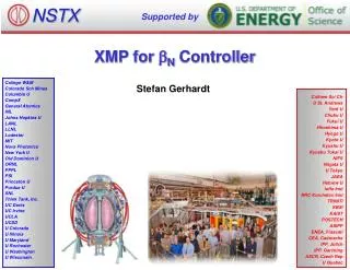
HHFW Conditioning XMP P. Ryan, J. Hosea, J. R. Wilson, G. Taylor, E. Fredd and anyone else who can stoke the furnace
XMP Objectives • Condition HHFW for high power operation • Withstand >25 kV at cubes in vacuum • Withstand ~15 kV at cubes in plasma for 200 ms pulses, phase shifts of 30º-180º. • Check out RF signals and diagnostics • Obtain loading vs power (estimate sheath losses) • Check out operation for upcoming XP scenarios • High plasma current operation • H-mode loading • NBI-driven plasmas • Duplicate conditions of 2004 (i.e., shots 107899, 107907)
Day 1 - Plain vanilla plasma, condition to highest power, scan phases to clean those hard to reach areas. • Day 0 - vacuum condition to 25 kV as per last year • Day 1 • Start with He operation, condition until 2 MW can be held for 180º and -90º. • Switch to D and repeat; see if there is any voltage degradation, local pressure rises during RF. • Condition +90º for same cube voltage limit. • Back to 180º, -90º and continue to increase power • Last hour of day: slow ramp to 600 kW at 180º, -90º, -30º, +30º, and +90º to check sheath loading.
Day 2 - Continue conditioning, develop operating techniques • Part 1 - more conditioning • Continue conditioning to 4 MW level (15 kV or greater on cubes) or until a hard voltage limit is reached. • Part 2 - check operation in future plasmas • High Ip (~900 kA) • NBI operation (high Ip and large gap) • NBI-driven H-mode plasma (steep density profiles)
500 kW 200 ms 300 ms 400 ms During conditioning, measure loading as a function of power to determine rf sheath losses. • Sheath power proportional to V, HHFW power proportional to V2. • Larger fraction of total power to sheath at low strap voltages. • At minimum, put a slow ramp down on low power conditioning pulse.
June 16 2005 - Rload vs P during conditioningIp = 600 kA, B0 = 0.45 T, He
June 16 2005 - Rload vs P during conditioningIp = 600 kA, B0 = 0.45 T, He
June 16 2005 - Rload vs P during conditioningIp = 600 kA, B0 = 0.45 T, He
June 16 2005 - Rload vs P during conditioningIp = 600 kA, B0 = 0.45 T, He
June 16 2005 - Rload vs P during conditioningIp = 600 kA, B0 = 0.45 T, He
June 16 2005 - Rload vs P during conditioningIp = 600 kA, B0 = 0.45 T, He