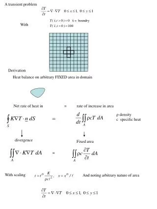

Role of Solid and Liquid Lithium Walls in LTX Confinement and Equilibrium
E N D
Presentation Transcript
Effect of solid and liquid lithium walls on confinement and equilibrium in LTX Dick Majeski • with: • R. Bell, D. Boyle, R. Kaita, T. Kozub, B. LeBlanc, M. Lucia, E. Merino, J. Schmitt, D. Stotler, G. Tchilingurian PPPL • T. M. Biewer, T. K. Gray ORNL • S. Kubota, W. A. Peebles,UCLA • C. Hansen, T. Jarboe, University of Washington • K. Tritz, Johns Hopkins University • J. Bialek,Columbia University • J. P. Allain, F. Bedoya, UIUC • Capece, B. Koel, Princeton University • K. Widman, P. Beiersdorfer, V. Soukhanovskii, F. Scotti, LLNL Supported by US DOE contracts DE-AC02-09CH11466 and DE-AC05-00OR22725
Outline • LTX features • Ohmically heated tokamak, R=40, a=26, 𝜅=1.6 • Hot, high Z shell construction • Lithium fill and electron beam evaporated coatings • Surface evolution of lithium coatings • Results with continuous high-field side gas fueling • Ohmic confinement with lithium PFCs • Core impurities • Electron temperature evolution when fueling is terminated • Implications for future operations • Plans for LTX-Upgrade • Summary
LTX features a hot, high Z, lithium compatible wall which incorporates lithium pools for evaporative coating Heat shielded centerstack 2-axis Mirnov coils Flux loops Fast, uncased internal coil 1.4 m Inner heated shell (explosively bonded SS on copper) Bottom of shells form reservoirs for up to 300 cm3 liquid lithium
Lithium delivery system uses a simple weighted piston • Lithium is delivered with a bellows-sealed motion stage • Dual gate valves (airlock) to prevent air exposure • Liquefy the lithium and it is ejected through outlet • Delivers 16 cm3 of lithium per fill • Multiple fills required for lithium pools • Electroformed tungsten crucible with outlet • Tungsten piston
Electron beam-based lithium evaporation system yields full lithium wall coatings Beam trajectory in guide fields (one beam shown) • Electron beams are magnetically guided by low (~70 G) quasi steady-state magnetic fields • Rapid electron beam-driven evaporation from lithium pools • Simultaneous operation of both e-guns coats all four shells at once Lithium pool Electron gun #1 < 1.5 kW Electron gun #2 < 2 kW
Coating sequence • Preheat shells to ~320 °C • Establish guide magnetic field • E-beam heat lithium pools • Maintain ~300 °C shell temperatue • Liquid lithium experiments • Shell heaters off for solid lithium • No performance degradation seen over a day’s run • Clean lithium requires near-elimination of residual water from vessel • Water level ~mid 10-10 Torr since lithium deposition initiated in late 2013 • Between-shots recoating possible in principle (but not in practice yet) Shell temperature rise during electron beam heating “Spangle” pattern on solidified lithium indicative of clean metallic coating
Successive lithium coating cycles have eliminated most water Late 2013 – After first few e-beam depositions -single e-beam coating half the shell • Background water 5-9 × 10⁻¹⁰ Torr • Oxygen 1-2 x 10⁻¹⁰ Torr • Hydrogen dominates RGA spectrum • Total pressure 2-3 × 10⁻⁸ Torr Now • Background water mid × 10-9 Torr • Oxygen 1-2 x 10⁻⁹ Torr • Hydrogen dominates RGA spectrum • Total pressure 3-5 × 10⁻⁸ Torr
Temporal evolution of lithium coatings • Analysis with the UIUC MAPP probe • MAPP has been moved to NSTX-U • Surface evolution of lithium-coated graphite, in NSTX-U vacuum, can be compared • Li:O ratio initially high • Ratios asymptotes to 2:1 • Indicates Li2O, not LiOH is formed in LTX • Timescale of surface evolution suggests between-shots coating capability might produce more metallic coatings
Ohmic discharges were used to estimate confinementwith e-beam evaporated lithium coatings Plasma current Stored energy Loop voltage βp Line average density Centerstack gas puffs βN • “Continuous” gas fueling with a centerstack gas nozzle
LTX exhibits improved ohmic confinement with solid and liquefied lithium PFCs • Only power input is Ohmic heating of electrons • te-i ~ 5 msec – ions weakly heated by electrons ➯Confinement improvement in electron channel • Effects of surface aging (passivation) clear • Any lithium coating improves performance relative to bare high-Z wall • Improvements in coating quality produce performance improvements • 4 hot shells • Full liquid lithium wall 2 hot shells Cold shells H98P(y,2) 2012 Helium dispersed coatings Passivated lithium • Good performance with 4 m2 liquefied lithium wall • Covers 80% of plasma LCFS
All impurities, including lithium very low, even with liquid lithium walls at 270 °C during gas fueling • Lithium core concentration < 0.5% • Estimate from concentration at peak in Li2+ emissivity • O < 0.05%, Carbon <0.1% • No significant core impurity accumulation for Z > lithium • Total Zeff from O, C, Li ~ 1.04 • No other impurity lines detected • Edge lithium concentration strongly depends on edge Te, ne • Large uncertainties with core Thomson • Edge Thomson would greatly improve accuracy • Gas puffing reduces edge Te • Lithium concentration significantly higher without gas puffing (~1-5%) emissivity peak Li2+
Flat electron temperature profile develops if edge gas load is removed • Longer discharges with new OH programming • All fueling (from centerstack) terminated at 462 msec • ~3-4 msec required to clear gas from duct • Te profile initially hollow, with strong fueling 467 msec LCFS 471 msec LCFS 464 msec LCFS • Peaked profile develops • Te profile evolves to flat or hollow, to LCFS • Edge electron temperature increases to 200 – 250 eV
Hot edge implies that ion impact energy can exceed the peak in the sputtering yield in LTX • Li sputtering yield for D incident on deuterated Li, calculations and IIAX measurements (Allain and Ruzic, Nucl. Fusion 42(2002)202). Angle of incidence 45° • At 700 eV the yield is 9% • Yield rises to slightly above 10%, just above the melting point • Yield is similar for D, H • Self-sputtering of Li on D-treated Li also drops with energy: • 24.5% at 700 eV • 15.8% at 1 keV • Probability of direct reflection of incident H from lithium PFC also drops to <10% for incident ion energy >500 eV
Upgrades are proposed for LTX in 2016 • Double toroidal field (0.17 T to 0.32 T) • Double energy in ohmic power supply • Ip ~ 150 kA • Longer flattop • Improve bakeout • Shell systems bakes to >300C, but vacuum chamber to 85 C • Improve chamber bakeout to 120 C • Increase vacuum pumping speed, address minor vacuum leaks • Add between-shots lithium coating capability • Expand diagnostic set • And add neutral beam injection for heating and fueling
2016 – Adding neutral beam injection to LTX-U system loaned to LTX by Tri-Alpha Energy • 17 – 23 kV, 35A, pulse length 30 – 50 msec • Paux significantly larger than Pohmic • Core fueling source • Tangency radius 23 cm as shown • R0 = 40 cm • 700 kW beam will also provide large toroidal momentum input • Beam system is now onsite
Summary • Experiments on LTX have now demonstrated good tokamak performance with full liquefied lithium walls • Lithium surface evolves to Li2O • Core impurity content low during gas puffing, even with hot wall • Edge electron temperature strongly increases with removal of edge gas load • Very flat Te profile develops • Discharge impurity content increases at most to 5% • Upgrades to LTX will extend tests to higher toroidal field, higher plasma current • Neutral beam adds auxiliary heating, modest core fueling capability • Upgrades to be complete in ~ 1 year
Recycling via direct reflection from lithium • Lithium has the lowest probability of direct reflection of any candidate PFC material • For an average incident angle of 45º, the reflection coefficient at low energy is ~20% (edge Te~30 eV) • Drops to <10% for edge Te ~ 300 eV Reflection Coefficient ITER School 2009 22-26 June 2009
Pt Sn Li Secondary electron effects • “Recycling” is typically thought of as an ion process • Electrons are also “recycled” via secondary electron emission • Secondaries cool the edge plasma. Power flow from the edge electron population to the wall/limiter/divertor: • For 0 = -(kTe/e), where 0 is the sheath potential at the wall/limiter/divertor, and typically ~3 • Lithium has the lowest secondary electron emission coefficient of any metal • Effect of secondaries in a magnetic field, in the edge plasma, is very difficult to model • Secondary electron emission is very sensitive to very thin (10s of Å) layers of surface impurities A. J. Dekker, in Solid State Physics, Advances in Research and Applications, Vol. 6 (Academic Press, New York, 1958) pp. 251-311
Ohmic discharge evolution without late fueling Gas valve HV drive signal Jumps due to OH IGBT control algorithm
Electron temperature profile evolution in LTX. Gas puffing is terminated at 462 msec. - Gas injection nozzle is emptied 3-5 msec after termination. outboard plasma edge (LCFS) Thomson scattering Te(R)
New equilibrium code (C. Hansen, U. Wash.) yields edge position in reasonable agreement with magnetics analysis Outboard edge from magnetics Outboard edge from magnetics • Magnetics estimate of plasma edge position uses two independent sets of diagnostic coils PSI-TRI code t=463 msec t=472 msec
Thomson Te vs normalized radius from equilibrium reconstruction (C. Hansen) • Edge data is noisy early and late in the discharge (low density)
Lithium safety • CDX/LTX experiments have run 15 years without incident • Extensive engineering controls for lithium systems • Secondary stand-by vacuum system (Roots blower) maintains reduced pressure in LTX, even if a vacuum window cracks • Tertiary turbopump system on 15 min. uninterruptible power • Heaters are interlocked to pressure sensors • ALL windows are mounted on gate valves • No direct water cooling of the vacuum boundary or internal sturctures • No argon gas pressurization to transfer liquid lithium • No use of demountable joints for lithium containment • Liquid lithium containment employs welded or formed stainless steel or tungsten structures • Vacuum boundary is NOT heated above the melting point of lithium • Lithium will freeze out on the wall. No possibility of egress into air