MEMS Based Storage Architecture for Relational Databases
490 likes | 750 Views
MEMS Based Storage Architecture for Relational Databases. Arjun Suresh S7, R College of Engineering Trivandrum. Outline. MEMS-based storage Relational database layout FRM (Flexible Retrieval Model) Query Processing on FRM Evaluation Conclusion. Building Storage on MEMS.

MEMS Based Storage Architecture for Relational Databases
E N D
Presentation Transcript
MEMS Based Storage Architecture for Relational Databases Arjun Suresh S7, R College of Engineering Trivandrum
Outline • MEMS-based storage • Relational database layout • FRM (Flexible Retrieval Model) • Query Processing on FRM • Evaluation • Conclusion
Building Storage on MEMS MEMS areMicro Electrical Mechanical Systems. • Basic functions: sensors and actuators • Built by standard silicon processing • Combine mechanical and electrical components • Enable “systems-on-a-chip”
Why need MEMS-based storage? • Huge gaps between disks and RAM • 1000,000 latency gap (10ms vs 50 ns), widening 50% yearly. • 1000 price gap per byte • 1000 life gap • MEMS narrows gaps • 10X smaller latency than disk • 100X cheaper than RAM in the range 1 – 10 GB • 100 MB - 1 GB/s bandwidth • 10 GB capacity with a penny size • Desired for energy and volume critical systems
EEPROM/Flash DRAM Cost per Byte MEMS-based Storage Hard Disk Latency Technology Trends
IBM Millipede • Using pits in the polymers made by tip heating to store data
Bits stored underneath each tip MEMS Storage Architecture Read/write tips Media side view
Y X MEMS Storage Architecture Media Sled
MEMS Storage Architecture Springs Springs Springs Springs
Y X MEMS Storage Architecture Anchor Anchor Anchors attach the springs to the chip. Anchor Anchor
Y X MEMS Storage Architecture Sled is free to move
Y X MEMS Storage Architecture Sled is free to move
Y X MEMS Storage Architecture Springs pull sled toward center
Y X MEMS Storage Architecture Springs pull sled toward center
Y X MEMS Storage Architecture Actuator Actuators pull sled in both dimensions Actuator Actuator
Y X MEMS Storage Architecture Actuators pull sled in both dimensions
Y X MEMS Storage Architecture Actuators pull sled in both dimensions
Y X MEMS Storage Architecture Actuators pull sled in both dimensions
Y X MEMS Storage Architecture Actuators pull sled in both dimensions
Y X MEMS Storage Architecture Probe tip Probe tips are fixed Probe tip
Y X MEMS Storage Architecture Probe tips are fixed
One probe tip per rectangle Sled only moves over the area of a single rectangle Each tip accesses data at the same relative position Y X MEMS Storage Architecture
Sweep area of One probe tip Properties of MEMS Storage
N bits M bits One tip sector Properties of MEMS Storage One tip region
Existing Work on Integration of MEMS Storage • Solution proposed by CMU researchers • Mapping MEMS storage into conventional disk • Adapt I/O scheduling and data placement to MEMS • Preliminary study shows • Reduce the I/O stall times by 4 to 74 times over disks • Improve the overall application run times by 1.9 to 4.4 • Reduce the energy consumption by 10-54 times
Better solutions?? • The approach of mapping MEMS into disk • Simplify the procedure of integration of MEMS • Does not consider the physical properties of MEMS
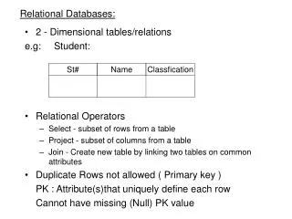
Relational Data Placement StudentGrade
N-ary Storage Model (NSM) • Store records in a relation in slotted disk pages • Organize records sequentially on the disk pages
Decomposition Storage Model(DSM) name perm ID • Divide a relation into sub-relations based on the number of attributes • Each sub-relation corresponds to each attribute • Each sub-relation is organized into pages in the same way as NSM A disk page A disk page age grade A disk page A disk page
Partition Attributes Across (PAX) • Within each page, PAX groups all values of each attribute into a mini-page • A page is divided into mini-pages based on the number of attributes • It stores the same data as NSM in each page A disk page
Common Workload Requirements • Relational data should be compatible with • OLTP workloads • Due to the update characteristics, relations need to be accessed in a row-wise manner • OLAP workloads • Only a subset of attributes is of interest, data placement should facilitate data retrieval on a column-wise fashion
Flexible Retrieval Model (FRM) • Facilitates data retrieval in both row-wise and column-wise manner • Retrieves the relevant subsets of the relations • Uses two dimensional layout of MEMS storage • Improves the I/O utilization • Maximize the concurrent tips to only retrieve the necessary data • It is also cache-friendly • Use intra-record locality
Attr1 Attr2 Attr3 (0, 0) (0, 1) (1, 2) (0, 2) (0, 2) (0, 2) (0, 2) (0, 0) (0, 1) (0, 0) (0, 1) (0, 0) (0, 1) FRM Data Placement and Retrieval • Given a relation with three attributes, the size of each attribute is 8 bytes • Placing this relation in 4x4 MEMS-based storage • 4 concurrent tips
Query Processing on FRM • Selection and projection without index • Two-dimensional table scan • Selection and projection with index • Encode data position as 4-tuple (tip-x, tip-y, offset-x, offset-y) • Joins • Index-based or hash
Experiment Setup • MEMS storage: 1280 concurrent tips out of 6400 total tips • Pentium II Celeron 433X2 processors • L1 cache:16KB, 32-byte cache line, 20 ns delay • L2 cache:128KB, 32-byte cache line, 200 ns delay • A relation R with 1.28 million records • Sixteen 8-byte attributes in each record • Queries: SELECT A1, A2,…, An FROM R WHERE A1 > Bound;
Memory utilization Consumed memory(MB) The selected attributes in queries
I/O performance • NSM and PAX have the same I/O time • I/O time of FRM is proportional to the size of retrieved attributes
Cache Utilization Selection Queries (2 attributes)
Projection Queries Selectivity = 50%
Projection Queries Selectivity =10%
Conclusion and Future Work • Proposed a relational data placement scheme for MEMS-based storage • Take advantage of two-dimensional MEMS access feature • Arrange MEMS rows and columns to relational attributes and records • Save IO cost and improve cache performance • Other cache friendly techniques for MEMS-based storage devices are to be explored