Download
1 / 17
170 likes | 300 Views
Multi Layered Pool Intrusion Detection System. TEAM G Orlando Carol Jay Cueco Rene Mendoza. Overview. Problem Statement Project Objectives Need Analysis Concept Development End Product Description Block Diagram Intellectual Property Standards Functions and Specifications

E N D
Multi Layered Pool Intrusion Detection System • TEAM G • Orlando Carol • Jay Cueco • Rene Mendoza.
Overview • Problem Statement • Project Objectives • Need Analysis • Concept Development • End Product Description • Block Diagram • Intellectual Property • Standards • Functions and Specifications • Project Milestones • Work Breakdown Structure (WBS) • Budget
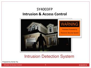
Problem Statement • The goal of this project is to design and develop a multi-layered swimming pool alarm system capable of detecting unauthorized intrusion in, and around the perimeter of a swimming pool. This product must be robust, marketable, and easily retrofitted. The device must be able to discriminate between a perimeter intrusion and a water surface intrusion.
Project Objectives • 1) Detect Intrusions • Detect pool perimeter intrusion • Detect pool water surface intrusion • 2) Provide Warning of intrusion • Visible warning of intrusion • Audible warning of intrusion • 3) Marketable • Economic • Easily retrofitted into pool area • Weatherproof • User friendly • 4) Safe • Unobtrusive to pool area • Electrically insulated from water • 5) Reliable • Differentiate between human intrusion versus other objects • Provide warning of intrusion quickly
Needs Analysis • The team decided to use the Fishbone diagram technique for needs analysis. • This technique helps to determine the root cause of a specific effect. • In our case, the effect is the drowning of a child at a swimming pool. • The team brainstormed on the possible places, procedures, people, or policies which have an effect on our problem. • Three causes were chosen: • Lack of Supervision • Ability of Child to Swim • Implementation of Preventative Measures • Survey was conducted to determine the most likely cause. • Lack of supervision was determined to be the most likely cause.
Child intrusion prevention of pool side area Electronic Non-electronic Water surface based sensors Fencing around pool Safety net on pool surface Perimeter based sensors Wave disturbance sensor Wearable electronic Underwater acoustic sensor Infrared Sonar Microwave Battery Powered Waterproof Casing Waterproof casing Digital Signal Processing Hydrophone Concept Development
End User Product Description • Two outdoor modules representing the perimeter based sensor and the subsurface based sensor. • One indoor receiver capable of receiving incoming signals from the two outdoor sensors. • One indoor alarm module capable of a visual flashing alarm and an audible alarm.
Perimeter Sensor Block Diagram Transmits constant waveform providing reference for normal environmental conditions Environment provides for dynamic ultrasonic information Receives dynamic ultrasonic information Logic circuit needed to check if the ultrasonic sensor detects an intrusion Provides remote power for system Battery Source Ultrasonic Transmitter Protected Environment Ultrasonic Receiver Microcontroller Wireless Transmitter In House Receiver Perimeter Alarm Receiver needed inside the house to turn on the perimeter alarm Unit contained in the house that will provide the owner with information about the perimeter pool side conditions Transmits the signal to turn on the perimeter sensor alarm Perimeter Sensor Block Diagram
Surface Sensor Block Diagram Receives the information from the signal processing and sends out the information needed to turn on and off the wireless transmitter Listens for the underwater acoustic conditions below the surface level Transmits the signal to turn on the surface sensor alarm Logic unit that will check if the underwater acoustic being received is a possible child Provides remote power for system Battery Source Passive Sonar Device Signal Processor Microcontroller Wireless Transmitter In House Receiver Perimeter Alarm Receiver needed inside the house to turn on the perimeter alarm Unit contained in the house that will provide the owner with information about the perimeter pool side conditions Subsurface Sensor Block Diagram
Intellectual Property • US Patent and Trademark Office database, patent # 6,642,847 was found to be a patent granted to Sison Co., for a pool alarm device. • The patent gives specific information as to the design of the device such as – the means of fastening the device to the pool, the way the detection device and transmitter are coupled, the sensors used for detection (infrared), etc. • In finding a suitable approach for design, it is important for the group not to infringe on patented designs.
Standards Consideration In 2002, and at the request of the U.S. Consumer Product Safety Commission, the American Society for Testing and Materials (ASTM) created a standard for swimming pool alarms known as ASTM F2208-02 : • 1. Alarm must sound at pool within 20 seconds. • 2. Remote alarm must sound at remote location within 20 seconds via a receiver. • 3. Alarm must have minimum sound pressure of 85 decibels at 10 feet. • 4. Alarm must have an on/off indicator. • 5. Alarm must have low-battery indicator. • 6. Alarm must automatically reset.
Functions and Specifications • 1 ) Detection of perimeter based intrusion – 30 feet around pool perimeter • 2 ) Detection of subsurface object – 15 pounds or heavier (average weight of 2 yr old child) • 3 ) Notification of owner – 20 second response minimal delay to allow for immediate action • 4 ) Waterproof/Windproof casing – winds of 20 mph (must be able to sustain outdoor elements without false alarm) Notice some specifications are in accordance with ASTM F2208-02.
Project Milestones The following accomplishments are the future milestones for the project: • 1. Research of possible technologies and selection. • 2. Design Initial Prototype. • Perimeter, Subsurface, In-House Receiver • 3. Test Initial Prototype • Each section separately followed by full system test. • 4. Modification of Prototype. • 5. Test Final Prototype • 6. Presentation of Device
LEGEND Build a Multiple Sensor Pool Alarm System Non Terminal Object Terminal Object Perimeter Sensor Subsystem Subsurface Sensor Subsystem Wireless Transmission and Reception Alarms Visual Perimeter Alarm Ultrasonic Sensor Transmitter Hydrophone Receiver Waterproof Housing Signal Processing Audible Surface Alarm Logic Circuit Battery Source Waterproof Housing Work Breakdown Structure