Download
1 / 18
190 likes | 212 Views
Learn about using Moon, Sun, and Galaxies radiation for calibrating RX antenna systems at mm-wave frequencies. Explore the sensitivity evaluations and temperature variations across lunar phases.

E N D
5th Sweden EME Meeting 2017 by SM4IVE, Örebro Calibrations of mm-wave antennas and RX systems using Moon radiation Dimitry FedorovUA3AVR 19-21 May 2017
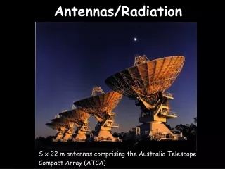
Radiometric sources in the sky • Radiometry at mm-waves. The sensitivity of RX+antenna system can be estimated or measured by comparing the output response to signals from different points of the sky.Therefore, space radio sources with a well known power at the RX input (in antenna aperture) are needed for tests. Looking up: • The Sun – the brightest source, but may be not convenient for testing of RX because of the sunspots radiation, see next slides ... • The Moon – emits the thermal radiation only, looks as a good source • Galaxies noise, maser lines (emission from molecular clouds) – too weak at mm-waves with moderate size antennas (dishes up to 2 m). • RW3BP tried to use the Jovian thermal radiation at 77 GHz, but flux is also faint, the RX response is about thousandths of dB with antenna D = 2.4 m, see http://www.vhfdx.ru/apparatura/eme-antenna-and-jupiter-noise-on-77-ghz.
The Sun: some details about this radiometric source • High flux level (solar thermal component is characterized by Tsun ~ 6000-7000 K) and good RX response using antennas with diameter D ~ meters and even <1 m • Beamwidth is usually narrow at millimeters, dHPBW ~ dSUN=0.5 deg and lower, antenna main beam may point to individual sunspots (2.4 m dish dHPBW = 0.12 deg at 77 GHz). Unfortunately, the level of sunspot radiation is not quite predictable, see also DUBUS 3/2016 p. 34 "Solar Flux and Temperature at Millimeter Waves“. Sunspots (visual picture – photosphere and magnetic map), late October 2014, Lebedev Physics institute, Moscow, http://www.tesis.lebedev.ru/sun_pictures.html?m=10&d=24&y=2014
Solar temperature at millimeters versus activity • MM-wave band lays close to transition zone from GHz range (with fair dependence on activity) to blackbodywith Tsun ~ 6000-7000 K. Thermal component is main but surprises are expected also. Solar Flux Index – SFI is usually measured at 2.7-2.8 GHz. • 24 GHz without surprises for now, data were collected while testing my new transverter in 2013 (ant. 0.6 m, RX NF=1.7 dB) … Above plot from: Christian Ho, Stephen Slobin, Anil Kantak, and Sami Asmar, Solar Brightness Temperature and Corresponding Antenna Noise Temperature at Microwave Frequencies, Interplanetary Network (IPN) Progress Report 42-175, pp. 1-21, November 15, 2008, http://tmo.jpl.nasa.gov/progress_report/42-175/175E.pdf. … but no regular experiments were made and 24 GHz researches are still needed
Higher frequencies … • At 38 GHz (lays close to 47 GHz band): the dependence on activity is seen using offset dish 0.9 m. • Quiet Sun temperature ~ 7000 K at 38 GHz. The radiation of individual sunspots at 38 GHz was seen by Salomonovich et all using 22 mm radio telescope (Astr. J. U.S.S.R. 39, p. 260, 1962, russian). My measurements of the solar temperature at 38 GHz see DUBUS 3/2016 p. 34 "Solar Flux and Temperature at Millimeter Waves" by UA3AVR • 76-77 GHz band is still a subject for investigations! Next: The Moon …
The Moon … • … is just a spherical body up in the sky heated by the Sun. Lunar radiation is thermal, no peculiar spots on the surface, strong magnetic fields, sporadic bursts etc. • Lunar temperature is well investigated, the Moon may be considered as a blackbody radiator at millimeter waves, but temperature changes with the lunar phase cycle, and there are temperature changes across lunar disc, the distribution of temperature is descending from center to edges, and form of distribution itself also varies during phase cycle. l=8.6 mm, moon phase 11.7 deg, waning gibbous, 0 deg is a full moon, by D.E. Clardy and A.W. Straiton, Radiometric Measurements of the Moon at 8.6- and 3.2-Millimeter Wavelengths, The Astrophysical Journal, v. 154, p. 775 (1968)
Lunar temperature distribution • Tmoon – temperature at the center of lunar disc, depends on the Phase FM (FM = 0 – corresponds to Full Moon). • The distribution for phases near Full Moon described by Gaussian function: r – angular distance from the center, dmoon – angular size of the Moon, s – the distribution’s parameter (taken according the picture by Clardy&Straiton from previous slide). Patricia R. Foster, Radio Observations in the Short Microwave Region, Quarterly Journal of the Royal Astronomical Society, v. 10, p.206 (1969) The blackbody model is accepted for the Moon, the noise temperature = thermodynamic temperature. Next: Antenna beamwidth and hM
Antenna beamwidth • So, if source in the sky is choosen, lets handle the next problem – antenna beamwidth is about angular size of the source disk. • If beamwidth is very narrow (like on background pic, src=moon, sun …) antenna should see a point at the source with temperature Tsrc. Tant – is a part of antenna temperature due to radiation of the source, hM – the Main beam efficiency, <1. Possible at mm-waves averaged • If beamwidth is very wide it should see a mean (averaged) temperature of the source over the seen disc. Wsrc – the solid angle of the source <<4p, Dmax – main lobe gain (directivity) of antenna. Usual for low frequency bands
For low- and medium-size mm-wave antennas … (intermediate case, some formulas) • Assuming a Gaussian form of the main lobe … (r – angle from the max) Antenna should see a mean temp of the source (weighted by main lobe form factor) • For dish with diameter d … (hA – Aperture efficiency) • Aperture efficiency versus Main beam efficiency … (calculated) • For typical dishes … See for reference: Daniel Minoli, Satellite Systems Engineering in an IPv6 Environment, CRC Press, 2009, pages 78-80 Next: Y-factor method
The Y-factor method … • ... is known to be applied for RX Noise Figure measurements, but may be used in radiometry, antenna calibration etc. • One should compare RX output when antenna looks to the Moon and on the cold sky. • Antenna should see on the sky: Thot – from the source (the Moon) radiation Tcold – from the Cosmic Microwave Background (CMB) • The Atmospheric attenuation and noise should be taken into account. To do that I followed to ITU recommendations "Attenuation by atmospheric gases" (P.676-10, Sep 2013) and "Radio noise" (P.372-9, Sep 2013). • Clear weather is needed, attenuation and additional noise from clouds and rain&snow is hardly predictable. • "Hot" (at the lunar max) and "Cold" RX output should be measured at the same elevation. • Full Moon or Phases nearby is essential. Image extracted from: D. Morabito, M. Gatti, and H. Miyatake, The Moon as a Calibration Load for the Breadboard Array, Interplanetary Network (IPN) Progress Report 42-172, pp. 1-21, February 15, 2008 Interesting facts and notes: • The CMB is shadowed by the lunar body • The quantum correction to CMB noise temperature TCMB=2.73 K may be up to 1 K (as it follows from the Planck’s law) for mm-waves.
If all parameters of RX system are known antenna should see … • Actual temperature Tmoon may be calculated using formulas by P. Foster, see slide 7. • Main beam efficiency hM was used as antenna performance characteristic. • If hM is not quite known one may use a typical value ~ 0.7, and then correct it up to the actual lunar temperature with above formula. • I used specially written calculator (for Excel spreadsheet), all big cumbersome formulas have been coded there. See screenshoots at the next slide… … temperature at the center of lunar disc. • Y – is the measured Y-factor • TCMB – the CMB temperature, ~ 2K • Latm – atmospheric attenuation factor, Latm >1, should be calculated a priori for actual weather. • Tatm – noise temperature of atmosphere (may be taken according ITU P.372, ~ 275 K) • Tsys=TRX+Tspill – RX system temperature (at the antenna aperture), TRX – is defined by RX Noise Figure, Tspill – the spillover temperature of antenna, could be estimated about 50-70 K (I used Tspill=70±30 K)
Calculate the lunar noise at millimeters quickly … Weather & elevation data: Actual lunar temperature Can be downloaded here: http://qsl.net/ua3avr/papers/Moon-Ground_Cal_2015+rus.zip
If more of parameters is not well known … • … an additional verification procedure can be applied. • For example, if RX Noise Figure is known estimately or with high uncertainty, • Antenna should be turned to ground outside (after Cold Sky measurement), and test RX system by the Ground thermal radiation. Formula for corresponding temperature The Ground temperature, as it seen by RX: • The Ground noise temperature should be about the same with indications of thermometer outside, ~ 280-290 K. As I guess, its uncertainty gap is also expected high, up to several tens of K. But poorly known NF of receiver could be verified (and, if needed, hM slightly corrected too). NEXT: about receiver (radiometer) 38 GHz
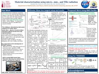
Radiometer (antenna+RX system) 38 GHz, built for solar measurements 2014-2015 Dish: 0.9 m Freq: 38 GHz NF: 5.5 dB IF1: 2500 MHz, IF2: 470 MHz BW: 120 kHz Averaging time: up to 10-15 s
Feed for dish – is pyramidal horn, matched to RX module using screws in the input waveguide. 38 GHz module RX3800-16 and LO module LCDFSL-1201MS – from eBay 1-st IF=2500 MHz is handled with MMDS-converter Gospell MDF-10T Schematic (block diagram): • Calibrated using the thermal radiation of the Moon, and was built for solar radio astronomy initially. • Averaging with t ~ 5-7 sec gives the opportunity to measure with detection accuracy <0.02 dB (for weak signals).
Parameters of 38 GHz radiometer after calibration … • Solar temperature versus activity • Quiet Sun value ~ 7000 K (meets the results of other researchers) Results …
Conclusion and notes … • The Moon appears as a good radiometric source for calibration of mm-wave RX with moderate size antennas (dishes up to 2 m). • Note: large size antennas require a higher profile accuracy of reflector for mm-waves. Phase errors (due to errors in shape) rise with frequency and lead to worsening of antenna performance. The gain degradation can be estimated with Ruse’s Equation, e – means here the RMS-error (or the fabrication tolerance) over reflector surface • Main beam efficiency hM appears to be a suitable characteristic for mm-wave antennas with narrow lobes. Objects in the sky (the Moon and the Sun) may be noticeably wider. Described calibration procedure takes into account uneven heating of the Moon’s surface. Some more works about using the Moon as a source for radiometry: [1] Jeffry Linsky, A Recalibration of the Quiet Sun Millimeter Spectrum Based on the Moon as an Absolute Radiometric Standard, Solar Physics, v.28, pp.409-418, 1973, SpringerLink: http://link.springer.com/article/10.1007%2FBF00152312, see also http://adsabs.harvard.edu/full/1973SoPh...28..409L [2] D. Morabito, M. Gatti, and H. Miyatake, The Moon as a Calibration Load for the Breadboard Array, Interplanetary Network (IPN) Progress Report 42-172, pp. 1-21, February 15, 2008, http://ipnpr.jpl.nasa.gov/progress_report/42-172/172G.pdf.
Thanks!5th Sweden EME Meeting by SM4IVEÖrebro, 19-21 May 201773 & and good luck in GHz EME!Dimitry Fedorov, UA3AVRua3avr@yandex.ru