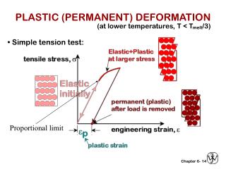
PLASTIC (PERMANENT) DEFORMATION
PLASTIC (PERMANENT) DEFORMATION. (at lower temperatures, T < T melt /3). • Simple tension test:. Proportional limit. 14. YIELD STRENGTH, s y. • Stress at which noticeable plastic deformation has occurred. when e p = 0.002=0.2% (just a rule of thumb or convention). 15.

PLASTIC (PERMANENT) DEFORMATION
E N D
Presentation Transcript
PLASTIC (PERMANENT) DEFORMATION (at lower temperatures, T < Tmelt/3) • Simple tension test: Proportional limit 14
YIELD STRENGTH, sy • Stress at which noticeableplastic deformation has occurred. when ep = 0.002=0.2% (just a rule of thumb or convention) 15
YIELD STRENGTH: COMPARISON Room T values Based on data in Table B4, Callister 6e. a = annealed hr = hot rolled ag = aged cd = cold drawn cw = cold worked qt = quenched & tempered 16
TENSILE STRENGTH, TS • Maximum possible engineering stress in tension. Adapted from Fig. 6.11, Callister 6e. Work Example Problem 6.3 • Metals: occurs when noticeable necking starts. • Ceramics: occurs when crack propagation starts. • Polymers: occurs when polymer backbones are aligned and about to break. 17
TENSILE STRENGTH: COMPARISON Room T values Based on data in Table B4, Callister 6e. a = annealed hr = hot rolled ag = aged cd = cold drawn cw = cold worked qt = quenched & tempered AFRE, GFRE, & CFRE = aramid, glass, & carbon fiber-reinforced epoxy composites, with 60 vol% fibers. 18
DUCTILITY, %EL • Plastic tensile strain at failure: Adapted from Fig. 6.13, Callister 6e. • Another ductility measure: • Note: %AR and %EL are often comparable. --Reason: crystal slip does not change material volume. --%AR > %EL possible if internal voids form in neck. 19
RESILIENCE Resilient materials, with high yield strength and low modulus of elasticity, are used in spring applications. 19
TOUGHNESS • • Energy to break a unit volume of material • • Approximate by the area under the stress-strain • curve. • Toughness can be measured with an impact test (Izod or Charpy) 20
TOUGHNESS Toughness can be measured with an impact test (Izod or Charpy) 20
TRUE STRESS & TRUE STRAIN necking Instantaneous area Instantaneous gauge length If volume of material is conserved during deformation: Ai li=A0 l0 Then 22
EXAMPLE PROBLEM 6.4 • A cylindrical specimen of steel having an original diameter of 12.8mm (0.505 in) is tensile tested to fracture and found to have an engineering fracture strength sf of 460 MPa (67,000 psi). If its cross-sectional diameter at fracture is 10.7mm (0.422 in). Determine: • The ductility in terms of percent reduction in area • The true stress at fracture 22
HARDENING strain • An increase in sy due to plastic deformation. • Curve fit to the stress-strain response: K K and n can be found from tables or tensile tests 22
HARDNESS • Resistance to permanently indenting the surface. • Large hardness means: --resistance to plastic deformation or cracking in compression. --better wear properties. Adapted from Fig. 6.18, Callister 6e. (Fig. 6.18 is adapted from G.F. Kinney, Engineering Properties and Applications of Plastics, p. 202, John Wiley and Sons, 1957.) 21
HARDNESS P Brinell, uses 10 mm sphere of steel or tungsten carbide Rockwell and Superficial Rockwell, uses a diamond cone (Brale indenter) or steel spheres Vickers microhardness, uses a diamond pyramid Knoop microhardness, uses a diamond pyramid 21
HARDNESS and TENSILE STRENGTH There is a linear relation between the tensile strength and hardness of a metal (especially for cast iron, steel and brass) For most steels: 21
DESIGN OR SAFETY FACTORS • Design uncertainties mean we do not push the limit. • Factor of safety, N Often N is between 1.2 and 4 • Ex: Calculate a diameter, d, to ensure that yield does not occur in the 1045 carbon steel rod below. Use a factor of safety of 5. 5 23
SUMMARY • Stress and strain: These are size-independent measures of load and displacement, respectively. • Elastic behavior: This reversible behavior often shows a linear relation between stress and strain. To minimize deformation, select a material with a large elastic modulus (E or G). • Plastic behavior: This permanent deformation behavior occurs when the tensile (or compressive) uniaxial stress reaches sy. • Toughness: The energy needed to break a unit volume of material. • Ductility: The plastic strain at failure. Note: For materials selection cases related to mechanical behavior, see slides 22-4 to 22-10. 24