Download
1 / 39
390 likes | 633 Views
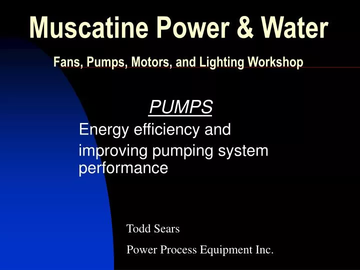
Muscatine Power & Water Fans, Pumps, Motors, and Lighting Workshop. PUMPS Energy efficiency and improving pumping system performance . Todd Sears . Power Process Equipment Inc. Pumps are the second most common machine in use today, they are exceeded in numbers only by electric motors

E N D
Muscatine Power & WaterFans, Pumps, Motors, and Lighting Workshop PUMPS Energy efficiency and improving pumping system performance Todd Sears Power Process Equipment Inc.
Pumps are the second most common machine in use today, they are exceeded in numbers only by electric motors • Pump represent 27% of the electricity consumed in the manufacturing sector
Pumping system components Typical pumping systems contain five basic components • Pump • Prime mover • Piping • Valves • End-user equipment (e.g. heat exchangers, tanks, other equipment)
WHAT IS THE PURPOSE OF A PUMP? • Pumps are designed to move fluid • Pumps transfer fluid for processing • In most plants pumps are a critical part of daily operation
Pump terms -Flow Measured in gallons per minute -Pressure Measured in PSIG -Head Measured in feet -Pump curve Displays flow, head & Eff. -Best efficiency point Relates to energy consumption -Cavitation Upset condition inside a pump -Deadhead No discharge flow from a pump -Suction, Discharge Fluid connections -Base Foundation for pump and driver -Alignment lining up pump shaft with driver
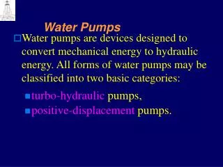
Pump types • Positive displacement Fixed displacement, fluid is captured in cavities within the pump and mechanical energy moves it from the inlet to discharge • Centrifugal Velocity is added to fluid by a spinning impeller and converted to pressure energy inside the pump. Pressure differential moves the fluid through the pump
Positive displacement pumps strengths • Low flow • High pressure • High viscosity • Self priming • Metering • High energy efficiency
Positive displacement pump concerns • Not for water thin fluids • Relief valves required • Solids can be a problem • Flow limited by size and speed • Pulsating flow • More complicated machine • May require speed reducers • Higher initial cost • Higher repair costs
Centrifugal pump strengths • High flow capability • Variable flow rates even at constant speed • Wide range of operation • Solids handling • Lower initial cost • Lower repair costs • Simple and safe to operate • Less wear with fewer replacement parts
Centrifugal pump concerns • Viscosity limitations • High pressure may require multiple impellers • Self priming issues • Lower energy efficiency • Piping system back pressure controls flow
Energy efficiency comparison Positive displacement vs. Centrifugal pumps • Conditions of service • 105 GPM • 48Cps • 80 PSIG discharge pressure PD pump -1750 RPM -9.2 HP -15 HP motor • Centrifugal pump • -3600 RPM • 13.2 HP • 20 HP motor 30% Horsepower difference Potential of over $1300/yr. savings
Common pump sizing issues • The importance of pumps to the daily operation of many facilities promotes the practice of conservatively sizing pumps to ensure that the needs of the system will be met under all conditions • In addition to inefficient operation, oversized pumps typically require more frequent maintenance than properly sized pumps
Oversized pumps • Oversizing pumps adds to system operating costs both in terms of energy and maintenance requirements -These costs are often overlooked during the system specification process • Since many of these operating and maintenance costs are avoidable, correcting an oversized pump can be a cost-effective system improvement
Indications of an oversized centrifugal pump • High flow noise • Highly throttled flow control valves • Heavy use of bypass lines • Frequent bearing and seal replacement • Intermittent pump operation
High flow noise • Oversized pumps tend to create high noise levels • The cumulative damage that results from flow-induced pipe vibrations can significantly accelerate system wear • Pump is running at high flow conditions and using extra energy
Throttled flow control valves • Throttle valves provide flow control in two ways: by increasing upstream backpressure, which reduces pump flow, and by directly dissipating fluid energy. • This dissipating of energy is an inefficiency that can be addressed
Bypass lines • Bypass lines prevent the buildup of damaging pressure differentials • The energy used to push fluid through bypass lines is wasted • A system that normally operates with a large number of open bypass valves indicates that the system is performing inefficiently due to improper balancing, oversized pumps, or both
Frequent bearing and seal replacement • Excess system flow can extend beyond high energy costs • Oversized pumps often operate far from their Best efficiency point (BEP) • They tend to experience greater bearing and seal wear
Moving towards “Shut-Off” BEP Pump Operating Point +/- 15% Extreme“Runout”
Hydraulic loads on the impeller BEP Impeller Radial Force High load Low load Capacity
Simultaneous loads on pump shaft Impeller Radial Thrust Impeller Axial Thrust Hydraulic Induced Forces due to Recirculation & Cavitation Seal or Packing Impeller Axial Thrust Radial Thrust due to Hydraulic Imbalance Hydraulic Imbalance
Head & flow impact on pump reliability Head 150 BEP 125 100 Impeller Damage Low Flow Cavitation 75 Suction Recirculation High Temperature Rise Bearing & Seal Life Reduced Discharge Recirculation 50 High Flow Cavitation 25 0 0 20 40 60 80 100 120 140 160 Capacity Presented by: S. Gopalakrishnan 5th International Pump Symposium Houston, TX
Intermittent Pump Operation • Pumps are often used to maintain fluid levels in tanks, either by filling or draining • Systems with level controls activate the pumps automatically • The cumulative effect of energizing and de-energizing a pump shortens the lives of the motor controller and the pump assembly
Ways to control flow of centrifugal pumps • Discharge throttle valves • Bypass valves • Impeller trimming • Speed control • Multiple pump arrangements The most appropriate flow control method depends on system size and layout, fluid properties, and system sensitivity to flow rate changes
Discharge throttle valves • Throttle valve chokes fluid flow such that less fluid can move through the valve, creating a pressure drop across it. • Throttle valves are more efficient than bypass valves. As the flow is limited the power required by the pump is reduced
Bypass valves • Bypass lines allow fluid to flow around a system component • Bypass lines increase system flow and require more power • The power used to pump the bypassed fluid is wasted
Impeller trimming • Impeller trimming refers to the process of machining the diameter of an impeller to reduce the energy added to the system fluid. • Impeller trimming offers a useful correction to pumps that are oversized for their application. • A 2 percent reduction in impeller diameter creates about a 2 percent reduction in flow, a 4 percent reduction in head, and an 8 percent reduction in power
When to consider impeller trimming • High noise or vibration levels exist indicating excessive flow. • Highly throttled discharge flow control valves. • Systems bypass valves are open, indicating excess flow available. Note: Impeller trim should be limited to 70% of full diameter
Variable speed control • Pump speed adjustments provide an efficient means of controlling pump flow. • By reducing pump speed, less energy is imparted to the fluid and less energy needs to be throttled or bypassed.
Multiple pump arrangements • Multiple pump arrangements are flexible, redundant, and have the ability to efficiently meet changing flow needs in systems with high static head components • Multiple pumps are usually parallel combinations of the same pump model to provide balanced load sharing during periods when all the pumps are operating
Systems approach to energy savings • The systems approach seeks to increase the efficiency of electric motor systems by shifting the focus from individual components and functions to total system performance. • In addition to energy savings, these improvements will yield a number of other economic benefits, including increased control over manufacturing processes, reduced maintenance, and higher levels of quality control.
Efficient pumping system considerations • Piping system layout that minimizes pressure drops • Larger pipes create less friction loss • Minimize unnecessary pressure drops by avoiding sharp bends, expansions, contractions, and where possible keep piping as straight as possible. • Use of low-loss components. valves, long sweep elbows, and components.
Pump system Life cycle costs • A highly efficient pumping system is not merely a system with an energy-efficient motor. • Overall system efficiency is the key to maximum cost savings. Often users are only concerned with initial cost, accepting the lowest bid for a component, while ignoring system efficiency. • To achieve optimum pumping system economics, users should select equipment based on life cycle economics and operate and maintain the equipment for peak performance.
References and sources for more information • Improving Pumping System Performance: A sourcebook for Industry. -Motor Challenge January 1999 • Cameron Hydraulic Data -Ingersoll Dresser Pumps • Pump Principals Manual, Form 07865 -A.W. Chesterton Company
Thank you • Todd Sears Power Process Equipment Inc. Cell 309-738-3481 Email: todds@ppei-mn.com Working with Industry to improve reliability