Shadows in Computer Graphics: Characteristics and Algorithms
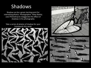
Explore the concept of shadows in computer graphics, including types, restrictions, and common algorithms. Learn about basic shadow components, shadow types, and the goal of shadow algorithms. Understand the characteristics of shadow algorithms and their computational complexity. Delve into the taxonomy of shadow algorithms, including object-based, image-based, and hybrid approaches. Discover important surveys on shadow algorithms for further insights.

Shadows in Computer Graphics: Characteristics and Algorithms
E N D
Presentation Transcript
Shadows Dinesh Manocha Computer Graphics COMP-770 lecture Spring 2009
What are Shadows? From Webster’s dictionary: Shad-ow (noun): partial darkness or obscurity within a part of space from which rays from a source of light are cut off by an interposed opaque body Is this definition sufficient?
What are Shadows? • Does the occluder have to be opaque to have a shadow? • transparency (no scattering) • translucency (scattering) • What about indirect light? • reflection • atmospheric scattering • wave properties: diffraction • What about volumetric or atmospheric shadowing? • changes in density Is this still a shadow?
What are Shadows Really? • Is this definition sufficient? • In practice, too general! • We need some restrictions Volumes of space that receive no light or lightthat has been attenuated through obscuration
Common Shadow Algorithm Restrictions • No transparency or translucency! • Limited forms can sometimes be handled efficiently • Backwards ray-tracing has no trouble with these effects, but it is much more expensive than typical shadow algorithms • No indirect light! • More sophisticated global illumination algorithms handle this at great expense (radiosity, backwards ray-tracing) • No atmospheric effects (vacuum)! • No indirect scattering • No shadowing from density changes • No wave properties (geometric optics)!
What Do We Call Shadows? • Regions not completelyvisible from a light source • Assumptions: • Single light source • Finite area light sources • Opaque objects • Two parts: • Umbra: totally blocked from light • Penumbra: partially obscured area light source shadow umbra penumbra
Basic Types of Light & Shadows area, direct & indirect area, direct only point, direct only directional, direct only SOFT SHADOWS HARD or SHARP SHADOWS more realistic simpler more realistic for small-scale scenes, directional is realistic for scenes lit by sunlight in space!
Goal of Shadow Algorithms • Shadow computation can be considered a global illumination problem • this includes ray-tracing and radiosity! • Most common shadow algorithms are restricted to direct light and point or directional light sources • Area light sources are usually approximated by many point lights or by filtering techniques Ideally, for all surfaces, find the fraction of lightthat is received from a particular light source
Global Shadow Component inLocal Illumination Model • Shadowi is the fraction of light received at the surface • For point lights, 0 (shadowed) or 1 (lit) • For area lights, value in [0,1] • Ambient term approximates indirect light Without shadows: With shadows:
What else does this say? • Multiple lights are not really difficult (conceptually) • Complex multi-light effects are many single-light problems summed together! • Superposition property of illumination model () • This works for shadows as well! • Focus on single-source shadow computation • Generalization is simple, but efficiency may be improved
Characteristics of Shadow Algorithms • Light-source types • Directional • Point • Area • Light transfer types • Direct vs. indirect • Opaque only • Transparency / translucency • Atmospheric effects • Geometry types • Polygons • Higher-order surfaces
Characteristics of Shadow Algorithms • Computational precision (like visibility algorithms) • Object precision (geometry-based, continuous) • Image precision (image-based, discrete) • Computational complexity • Running-time • Speedups from static viewer, lights, scene • Amount of user intervention (object sorting) • Numerical degeneracies
Characteristics of Shadow Algorithms • When shadows are computed • During rendering of fully-lit scene (additive) • After rendering of fully-lit scene (subtractive)not correct, but fast and often good enough • Types of shadow/object interaction • Between shadow-casting object and receiving object • Object self-shadowing • General shadow casting
Taxonomy of Shadow Algorithms • Object-based • Local illumination model (Warnock69,Gouraud71,Phong75) • Area subdivision (Nishita74,Atherton78) • Planar projection (Blinn88) • Radiosity (Goral84,Cohen85,Nishita85) • Lloyd (2004) • Image-based • Shadow-maps (Williams78,Hourcade85,Reeves87, Stamminger/Drettakis02, Lloyd 07) • Projective textures (Segal92) • Hybrid • Scan-line approach (Appel68,Bouknight70) • Ray-tracing (Appel68,Goldstein71,Whitted80,Cook84) • Backwards ray-tracing (Arvo86) • Shadow-volumes (Crow77,Bergeron86,Chin89)
Good Surveys of Shadow Algorithms Early complete surveys found in (Crow77 & Woo90) Recent survey on hard shadows: Lloyd 2007 (Ph.D. thesis) Recent survey on soft shadows: Laine 2007 (Ph.D. thesis)
Survey of Shadow Algorithms Focus is on the following algorithms: • Local illumination • Ray-tracing • Planar projection • Shadow volumes • Projective textures • Shadow-maps Will briefly mention: • Scan-line approach • Area subdivision • Backwards ray-tracing • Radiosity
Local Illumination “Shadows” • Backfacing polygons are in shadow (only lit by ambient) • Point/directional light sources only • Partial self-shadowing • like backface culling is a partial visibility solution • Very fast (often implemented in hardware) • General surface types in almost any rendering system!
Local Illumination “Shadows” • Typically, not considered a shadow algorithm • Just handles shadows of the most restrictive form • Dramatically improves the look of other restricted algorithms
Local Illumination “Shadows” Properties: • Point or directional light sources • Direct light • Opaque objects • All types of geometry (depends on rendering system) • Object precision • Fast, local computation (single pass) • Only handles limited self-shadowing convenient since many algorithms do not handle any self-shadowing • Computed during normal rendering pass • Simplest algorithm to implement
Ray-tracing Shadows Only interested in shadow-ray tracing (shadow feelers) • For a point P in space, determine if it is shadow with respect to a single point light source L by intersecting line segment PL (shadow feeler) with the environment • If line segment intersects object, then P is in shadow, otherwise, point P is illuminated by light source L L shadow feeler(edge PL) P
Ray-tracing Shadows • Arguably, the simplest general algorithm • Can even handle area light sources • point-sample area source: distributed ray-tracing (Cook84) Area light Li Li P P Shadowi = 0 Shadowi = 2/5
Ray-tracing Shadows • Slow • Intersection tests are (relatively) expensive • May be sped up with standard ray-tracing acceleration techniques • Shadow feeler may incorrectly intersect object touching P • Depth bias • Object tagging • Don’t intersect shadow feeler with object touching P • Works only for objects not requiring self-shadowing Sounds great, what’s the problem?
Ray-tracing Shadows How do we use the shadow feelers? 2 different rendering methods • Standard ray-casting with shadow feelers • Hardware Z-buffered rendering with shadow feelers
Ray-tracing Shadows Ray-casting with shadow feelers For each pixel: • Trace ray from eye through pixel center • Compute closest object intersection point P along ray • Calc Shadowi for point by performing shadow feeler intersection test • Calc illumination at point P Light Eye
Ray-tracing Shadows Z-buffering with shadow feelers • Render the scene into the depth-buffer (no need compute color) • For each pixel, determine if in shadow: • “unproject” the screen space pixel point to transform into eye space • Perform shadow feeler test with light in eye space to compute Shadowi • Store Shadowi for each pixel • Light the scene using per-pixel Shadowi values Light Eye
Ray-tracing Shadows Z-buffering with shadow feelers How do we use per-pixel Shadowi values to light the scene? • Method 1: compute lighting at each pixel in software • Deferred shading • Requires object surface info (normal, materials) • Could use more complex lighting model
Ray-tracing Shadows Z-buffering with shadow feelers How do we use per-pixel Shadowi values to light the scene? • Method 2: use graphics hardware • For point lights: • Shadowi values either 0 or 1 • Use stencil buffer, stencil values = Shadowi values • Re-render scene with the corresponding light on using graphics hardware but use stencil test to only write into lit pixels (stencil=1). Should perform additive blending and ambient-lit scene should be rendered in depth computation pass. • For area lights: • Shadowi values continuous in [0,1] • Multiple-passes and modulation blending • Pixel Contribution = Ambienti + Shadowi*(Diffusei+Speculari)
Ray-tracing Shadows Properties • Point, directional, and area light sources • Direct light (may be generalized to indirect) • Opaque (thin-film transparency easily handled) • All types of geometry (just need edge intersection test) • Hybrid : object-precision (line intersection), image-precision for generating pixel rays • Slow, but many acceleration techniques are available • General shadow algorithm • Computed during illumination (additive, but subtractive is possible) • Simple to implement
Planar Projection Shadows • Shadows cast by objects onto planar surfaces • Brute force: project shadow casting objects onto the plane and draw projected object as a shadow Directional light(parallel projection) Point light(perspective projection)
Planar Projection Shadows Not sufficient • co-planar polygons (Z-fighting) : depth bias • requires clipping to relevant portion of plane : shadow receiver stenciling
Planar Projection Shadowsbetter approach, subtractive strategy Render scene fully lit by single light For each planar shadow receiver: • Render receivers: stencil pixels covered • Render projected shadow casters in a shadow color with depth testing on, depth biasing (offset from plane), modulation blending, and stenciling (to write only on receiver and to avoid double pixel writing) • Receiver stencil value=1, only write where stencil equals 1, change to zero after modulating pixel Texture is visible in shadow
Planar Projection Shadowsproblems with subtractive strategy • Called subtractive because it begins with full-lighting and removes light in shadows (modulates) • Can be more efficient than additive (avoids passes) • Not as accurate as additive. Doesn’t follow lighting model • Specular and diffuse components in shadow • Modulates ambient term • Shadow color is chosen by user as opposed to the correct version
Planar Projection Shadowseven better approach, additive strategy • Draw ambient lit shadow receiving scene (global and all lights’ local ambient) • For each light source:For each planar receiver • Render receiver: stencil pixels covered • Render projected shadow casters into stenciled receiver area: depth testing on, depth biasing, stencil pixels covered by shadow • Re-render receivers lit by single light source (no ambient light): depth-test set to EQUAL, additive blending, write only into stenciled areas on receiver and not in shadow • Draw shadow casting scene: full-lighting
Planar Projection ShadowsProperties • Point or directional light sources • Direct light • Opaque objects (could fake transparency using subtractive) • Polygonal shadow casting objects, planar receivers • Object precision • Number of passes: L=num lights, P=num planar receivers • subtractive: 1 fully lit pass, L*P special passes (no lighting) • additive: 1 ambient lit pass, 2*L*P receiver passes, L*P caster passes
Planar Projection ShadowsProperties • Can take advantage of static components: • static objects & lights: precompute silhouette polygon from light source • static objects & viewer: precompute first pass over entire scene • Visibility from light is handled by user(must choose casters and receivers) • No self-shadowing (relies on local illumination) • Both subtractive and additive strategies presented • Conceptually simple, surprisingly difficult to get right gives techniques needed to handle more sophisticated multi-pass methods
Shadow VolumesWhat are they? Volume of space in shadow of a single occluder with respect to a point light source OR Volume of space swept out by extruding an occluding polygon away from a point light source along the projector rays originating at the pointlight and passing through the vertices of the polygon point light occluding triangle 3D shadow volume
Shadow VolumesHow do you use them? • Parity test to see if a point P on a visible surface is in shadow: • Initialize parity to 0 • Shoot ray from eye to point P • Each time a shadow-volume boundary is crossed, invert the parity • if parity=0, P is in shadowif parity=1, P is lit What are some potential problems? point light eye 0 occluder 0 0 1 1 0 parity=0 parity=1 parity=0
Shadow VolumesProblems with Parity Test • Incorrectly shadows pts(reversed parity) • Should a point on the occluder flip the parity?(consistent if not flipped) Eye inside of shadow volume Self-shadowing of visible occluders Multiple overlapping shadow volumes 0 0 0 0 1 0 1 0 1 0 • Point on the occluder should not flip the parity • Touching boundary is not counted as a crossing • Incorrectly shadows pts (incorrect parity) • Is parity’s binary condition sufficient?
Shadow VolumesSolutions to Parity Test Problems • Init parity to be 0 when starting outside and 1 when inside • Do not flip parity when viewing the “in”-side of an occluder Eye inside of shadow volume Self-shadowing of visible occluders Multiple overlapping shadow volumes 0 1 +1 +1 -1 -1 1 1 0 0 1 2 1 0 • Do not flip parity when viewing “out”-side of an occluder either • Binary parity value is not sufficient, we need a general counter for boundary crossings: +1 entering a shadow volume, -1 exiting
+1 +1 -1 -1 0 1 2 1 0 Shadow VolumesA More General Solution Determine if point P is in shadow: • Init boundary crossing counter to number of shadow volumes containing the eye pointWhy? Because ray must leave this many shadow volumes to reach a lit point • Along ray, increment counter each time a shadow volume is entered, decrement each time one is exited • If the counter is >0, P is in shadow Special case when P is on an occluder • Do not increment or decrement counter • Point on boundary does not count as a crossing
Shadow VolumesMore Examples Can you calculate the final boundary count for these visible points?
Shadow VolumesMore Examples Can you calculate the final boundary count for these visible points? 1 0 +1 +1 1 +1 -1 +1 +1 -1 1 +1 -1 -1 0 2 0 0
Shadow VolumesHow do we use this information to find shadow pixels? Could just use ray-casting (ray through each pixel) • Too slow, possibly more primitives to intersect with • Could use silhouette of complex objects to simplify shadow volumes 0 0 1 + - + - + 1 + - 0 - + - + + + + - - + + - + 0 + - + + - + 1 0 2 1
Shadow VolumesUsing Standard Graphics Hardware Simple observations: • For convex occluders, shadows volumes form convex shape. • Enter through front-facing shadow-volume boundariesExit through back-facing 0 0 1 + - + - + 1 + - 0 - + - + + + + - - + + - + 0 + - + + - +
Shadow VolumesUsing Standard Graphics Hardware Use standard Z-buffered rendering and the stencil buffer (8 bits) to calculate boundary count for each pixel • Create shadow volumes for each occluding object (should be convex) • Render the ambient lit scene, keep the depth values • For each light source • Initialize stencil values to number of volumes containing the eye point • Still using the Z-buffer depth test (strictly less-than), but no depth update • Render the front-facing shadow-volume boundary polygons, increment stencil values for all pixels covered by the polygons that pass the depth test • Render the back-facing boundary polygons, but decrement the stencil. • Pixels with stencil value of zero are lit, re-render the scene with lighting on (no ambient, depth-test should be set to equal).
Shadow VolumesUsing Standard Graphics Hardware: step-by-step • Create shadow volumes • Initialize stencil buffer valuesto # of volumes containing eye per-pixel stencil values initially 0
Shadow VolumesUsing Standard Graphics Hardware: step-by-step • Render the ambient lit scene • Store the Z-buffer • Set depth-test to strictly less-than
Shadow VolumesUsing Standard Graphics Hardware: step-by-step • Render front-facing shadow-volume boundary polygons • Why front faces first? Unsigned stencil values • Increment stencil values for pixels covered that pass depth-test
Shadow VolumesUsing Standard Graphics Hardware: step-by-step • Render back-facing shadow-volume boundary polygons • Decrement stencil values for pixels covered that pass depth-test
Shadow VolumesUsing Standard Graphics Hardware: step-by-step • Pixels with stencil value of zero are lit • Set depth-test to strictly equals • Re-render lit scene with no ambient into lit pixels