Download
1 / 46
480 likes | 847 Views
Optical Aberrations and Aberrometry F. Karimian, MD 2002.

E N D
AberrationsPerfect Eye would image every infinitesimal point in a scene to a corresponding infinitesimal small point on retinaNo blurring for each pointWavefronts are perfectly spherical emanate outward, diverge from pointPerfect Eye: converts diverging spherical waves into converging wavesconverging waves must be converge to a perfectly spherical point on retina
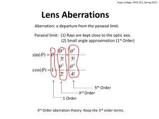
Perfect imaging Never occurs at periphery - diffraction- interaction with pupil margin Aberration = Deviation of changing wave fronts from perfect sphere
Monochromatic Aberrations Aberrations for a specific wavelength of visible light Classifications: - Spherical refractive error (defocus) Cylindrical refractive error (astigmatism) Spherical aberration Coma Higher-order aberrations
Chromatic Aberrations • Depends upon the color or light wavelength • Causes:- light dispersion in the cornea, aqueous, crystalline lens and vitreous -Variation index of refraction • Refractive surgery techniques CANNOT correct chromatic aberrations • Spectral sensitivity of the eye helps to reduce the effects of chromatic aberration
Yesterday!optical imperfection and aberrationsOnly theory No clinical practice Today! laser refractive surgery potential for correction Needs knowledge
Measurement of Optical Quality -By three common methods Method I : - Description of detailed shape of the image for a simple geometrical object e.g. a point or line of light PSF (point spread function): distribution of light in the image plane for a point LSF (line spread function): distribution for a line object Blurring effects: blur circle diameter (width of image) Strehl ratio (height)
Method II • Description of the loss of contrast in image of a sinusoidal grating object • Sinusoidal grating objects aberrations of the imaging system remains the same over the full extent of the object i.e. “preservation form” • Ratio of image contrast to object contrast blurring effect of optical imperfections • Variation of this ratio with spatial frequency Modulation transfer function (MTF)
Methods II… cont.. -Difference between spatial phase of image and phase of the object + variation with spatial frequency and orientation of the grating Phase transfer function (PTF) -MTF + PTF Optical transfer function (OTF) Fourier Transform: -Mathematical linkage of PSF, LSF, MTF, PTF, OTF -Computing the retinal image (naturally inaccessible) for any visual object
Method III • Specifying optical quality in terms of optical aberrations • Description: Ray aberrations (deviation of light rays from perfect reference ray) • Wave front aberrations (deviation of optical wave fronts from ideal wave front) • Aberrometry: description of optical imperfections of the eye • All secondary measures of optical quality (PSF,LSF,MTF,PTF, and OTF) may be derived • Useful approach for customized corneal ablation
Definition and Interpretation of Aberration Maps Optical Path Length (OPL): number of times a light wave must oscillate in traveling from one point to another - product of physical path length with refractive index Optical Path Difference (OPD): - comparing the OPL for a ray passing in the plane of exit pupil with the chief ray passing through pupil center - optical aberrations are differences in optical path difference
Causes of Aberrations • Thickness anomalies of the tear film, cornea, lens, anterior chamber, post chamber • Anomalies of refractive index in ocular media due to aging, inflammation, etc. • Decentering or tilting the various optical components of the eye
Optimum retinal image same optical distance for all object point • Wavefront aberration map shows extent of violated ideal condition Reversing the direction of light propagation Map of OPD across the pupil plane shape of aberrated wave front
History of Measuring Aberration Maps Scheiner (1619) Scheiner’s disk with 2 pinholes single distant point of light optically imperfect eye 2 retinal image Porterfield (1747) used Scheiner disk to measure refractive error Smirnov used Scheiner method central fixed and moveable light source for outer pinhole Adjusting outer source horizontal or vertical Redirect outer light patient reports seeing single point
Hartmann method numerous holes in opaque screen each hole aperture for a narrow ray bundle Tracing errors in direction of propagation Error in wavefront slope Shack & Platt an array of tiny lenses focusing into an array of small spots Measuring displacement for each spot from lenslet axis Shape of aberrated wavefront (Shack-Hartmann)
Liang (1994): Used Shack-Hartmann Wavefront sensor for Human Eye 2 relay lenses focusing lenslet array onto the entrance pupil Subdividing the reflected wavefront immediately as it emerges from the eye Spot images formed capture by a video sensor computer analysis
Taxonomy of Optical Aberrations • Transverse ray aberration (slope): Angle (t) between aberrated ray and the non- aberrated reference ray • Longitudinal ray aberration: focusing error = 1/z (diopters) = transverse aberration/ ray height at pupil plane
If aberration is defocus Longitudinal aberration is constant = spherical refractive error Coma or spherical aberration longitudinal aberration varies with pupil location Rate of slope of wavefront (i.e: local curvature) in horizontal and vertical directions Laplacian map of the aberration ( in diopters)
PSF and Strehl’s Ratio PSF = Squared magnitude of Fourier transform Strehl’s Ratio = actual intensity in the center of spot maximum intensity of a diffraction – limited spot Pupil diameter intensity of a diffraction – limited – spot PSF have multiple peaks 2 or more point images for single point Di- or polyplopia Pupil diameter excludes most of aberrations Much improved image quality clearer more focused retinal image
Zernike Polynomials Wavefront shape representation in polar coordinates (r/q) r = radial distance from pupil center q = angle of the semi meridian for a given point on the wavefront
Ordering of Aberrations Wavefront (difference in shape between the aberrated wave front from ideal wave front ) for myopia, hyperopia and astigmatism second order Coma is third order aberration = wavefront error is well fit with third order polynomial Spherical aberration is fourth order aberration.
Corneal Topography Vs. Wavefront Topography: - Utilizes information from the corneal surface - Two – dimensional mapping profile of keratometry Wavefront measurement device: - Two dimensional profile of refractive error - Used to attempt to smooth corneal points on the retinal fovea
Principles of Wavefront Measurement Devices Three Different principles by which, wavefront aberration is collected and measured: 1-Outgoing Reflection Aberrometry (Shack – Hartmann) 2- Retinal lmaging aberrometry (Tscherning and Ray Tracing) 3- Ingoing Adjustable Refractometry (Spatially Resolved Refractometer)
Outgoing Reflection Aberrometry (Shack – Hartmann) In 1994:Liang and Bill used Shack- Hartmann principle In 1996: Adaptive optics as defined by Shack- Hartmann sensor use to view cone photoreceptors Shack- Hartmann wavefront sensor utilizes >100 spots, created by (> 100) lenslets The aberrated light exiting the eye CCD detection Distance of displaced (dx) focused spot from ideal shows aberration.
Outgoing Reflection aberrometry … (cont.) Limitation: Multiple scattering from choroidal structures, interference echo insignificant in comparison to axial length
Retinal Imaging Aberrometry (Tscherning and Ray Tracing) In 1997:Howland & Howland used Tscherning aberroscope design together with a cross cylinder Seilor: used a spherical lens to project a 1mm grid pattern onto the retina Para- axial aperture system visualization and photography of aberrated pattern
Tscherning and Ray Tracing (cont.) Limitation: -This wave front sensing used an idealized eye model (Gullstrand) -The eye model is modified according to patient’s refractive error Tracey Retinal ray tracing: slightly different - Uses a sequential projection of spots onto the retina - Captured and traced to find wavefront pattern - 64 sequential retinal spots can be traced in 12 ms
Ingoing Adjustable Refractometry (Spatially Resolved Refractometer) In 1961: - Smirnov used scheiner principle subjective adjustable refractometry Peripheral beams of incoming light are subjectively redirected to a central target to cancel ocular aberrations In 1998: Webb and Bums used spatially Resolved refractometer (SRR) 37 testing spots are manually directed to overlap the central target Limitation: - Lengthy time for subjective alignment
Ingoing adjustable Refractometry …(cont.) Objective variant: Slit retinoscopy rapid scanning along specific axis and orientation Capture of fundus reflection wavefront aberration
Commercial Wavefront Devices Outgoing ReflectionRetinal lmagingIngoing adjustable Abberrometry Abberrometry Refractometry Shack-Hartmann principles Tscherring principle Scheiner principles Alcon summit/ Autonomous wave light wavefront Emory vision SRR analyzer Nidek OPD scan Custom cornea meas.device Schwind wavefront (slit skioloscopy) analyzer VisX 20/10 perfect vision Tracey retinal ray wavescan tracing Bausch & Lomb zyoptics Aesculap Medical WOSCA
Careful comparison of various wavefront measuring principles and their specific devices has not yet been performed clinically